24
20303735
VWDV70 Series Gas Fireplace
FIrepLace InstaLLatIon
checK Gas type
Use proper gas type for the fireplace you are installing.
If you have conflicting gas type, do not install fireplace.
See dealer where you purchased the fireplace for proper
fireplace for your gas type or conversion kit.
InstaLL Gas pIpInG to FIrepLace
LocatIon
InstaLLatIon IteMs neeDeD
Before installing fireplace and burner system, make sure
you have the items listed below.
•
External regulator (supplied by installer)
•
Piping (check local codes)
•
Equipment shutoff valve*
•
Sealant (resistant to propane/LP gas)
•
Test gauge connection*
•
Sediment trap (recommended)
•
Tee joint
•
Pipe wrench
•
Approved flexible gas line with gas connector (if
allowed by local codes — not provided)
* A CSA design-certified equipment shutoff valve with
1/8" NPT tap is an acceptable alternative to test gauge
connection. Purchase the CSA design-certified equip-
ment shutoff valve from your dealer.
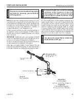
For propane/LP connections only, the installer must supply
an external regulator. The external regulator will reduce
incoming gas pressure. You must reduce incoming gas
pressure to between 11 and 13 inches of water. If you do
not reduce incoming gas pressure, burner system regula-
tor damage could occur. Install external regulator with the
vent pointing down as shown in
Figure 35.
Pointing the
vent down protects it from freezing rain or sleet.
W
arn
In
G
a qualified installer or service person must
connect appliance to gas supply. Follow
all local codes.
caut
Ion
For propane/Lp units, never connect
fireplace directly to the propane/Lp supply.
this burner system requires an external
regulator (not supplied). Install the external
regulator between the burner system and
propane/Lp supply.
FP1977
external regulator
Figure 35 -
External Regulator with Vent Pointing Down
(Propane/LP Only)
FP1977
External
Regulator
100 gallon (min)
Propane/LP Supply
Tank
Vent Pointing
Down
caut
Ion
use only new black iron or steel pipe.
Internally tinned copper or copper tubing
can be used per national Fuel code, section
2.6.3, providing gas meets hydrogen sulfide
limits, and where permitted by local codes.
Gas piping system must be sized to provide
minimum inlet pressure (listed on data plate)
at the maximum flow rate (Btu/hr). undue
pressure loss will occur if the pipe is too
small.
When using copper of flex connectors use only fittings
approved for gas connections. The gas control inlet is
3/8" NPT.
The gas control is equipped with a captured screw type
pressure test point, therefore it is not necessary to provide
a 1/8" test point up stream of the control.
Always provide a union when using black iron pipe so
the gas line can be easily disconnected for burner or fan
servicing. Refer to gas specifications for pressure details
and ratings.
The fireplace valve must not be subjected to any test pres-
sures exceeding 1/2 psi. Isolate or disconnect this and
any other gas appliance control from the gas line when
pressure testing.

