Every Year:
●
Replace the exhaust filter (
Ú
Change of the Exhaust Filter)
In case an inlet air filter is installed:
◆
Replace the inlet air filter
●
Check the inlet screen (f, 261), clean if necessary
●
Replace the filter of the gas ballast (d, 440)
Every 500 - 2000 Operating Hours:
Observe the operating instructions from the manufacturer of the ma-
chine which the vacuum pump has become a part of.
●
Change the oil (
Ú
Oil Change)
Oil Change
After switching off the vacuum pump at normal operating temperature
wait no more than 20 minutes before the oil is drained (the oil shall still
be warm when being drained).
●
Completely drain the used oil (h)
●
Remove the cover of the cleaning port (k), check the oil sump for
residues, mechanically remove the residues if necessary
●
Fill in approx. 0.3 litres of vacuum pump oil (a)
●
Dispose of the used oil in compliance with applicable regulations
Change of the Exhaust Filter
Eye protection goggles must be worn while changing
the exhaust filter!
●
Make sure that the vacuum pump is shut down and locked against
inadvertent start up
●
Remove the exhaust cover (g) from the oil separator (j)
●
Loosen the screw in the centre of the exhaust filter retaining
spring, but do not remove it at this time
●
Press the exhaust filter retaining spring out of the indent and ro-
tate it
●
Remove the exhaust filter retaining spring from the oil separator (j)
●
Pull the exhaust filter out of the oil separator (j)
●
Install the new exhaust filter in reverse order
●
Dispose of the used exhaust filter in compliance with applicable
regulations
Dismantling and Disposal
The inside of the vacuum pump, the oil and the exhaust filter can be
contaminated with process residues: wear personal protective equip-
ment as appropriate!
●
Drain the oil and dispose of it in compliance with applicable regula-
tions
●
Remove the exhaust filter (
Ú
Change of the Exhaust Filter) and
dispose of it in compliance with applicable regulations
●
Make sure that the vacuum pump is not contaminated with harm-
ful foreign material
According to the best knowledge at the time of printing of this manual
the materials used for the manufacture of the vacuum pump involve
no risk.
●
Dispose of the vacuum pump as scrap metal
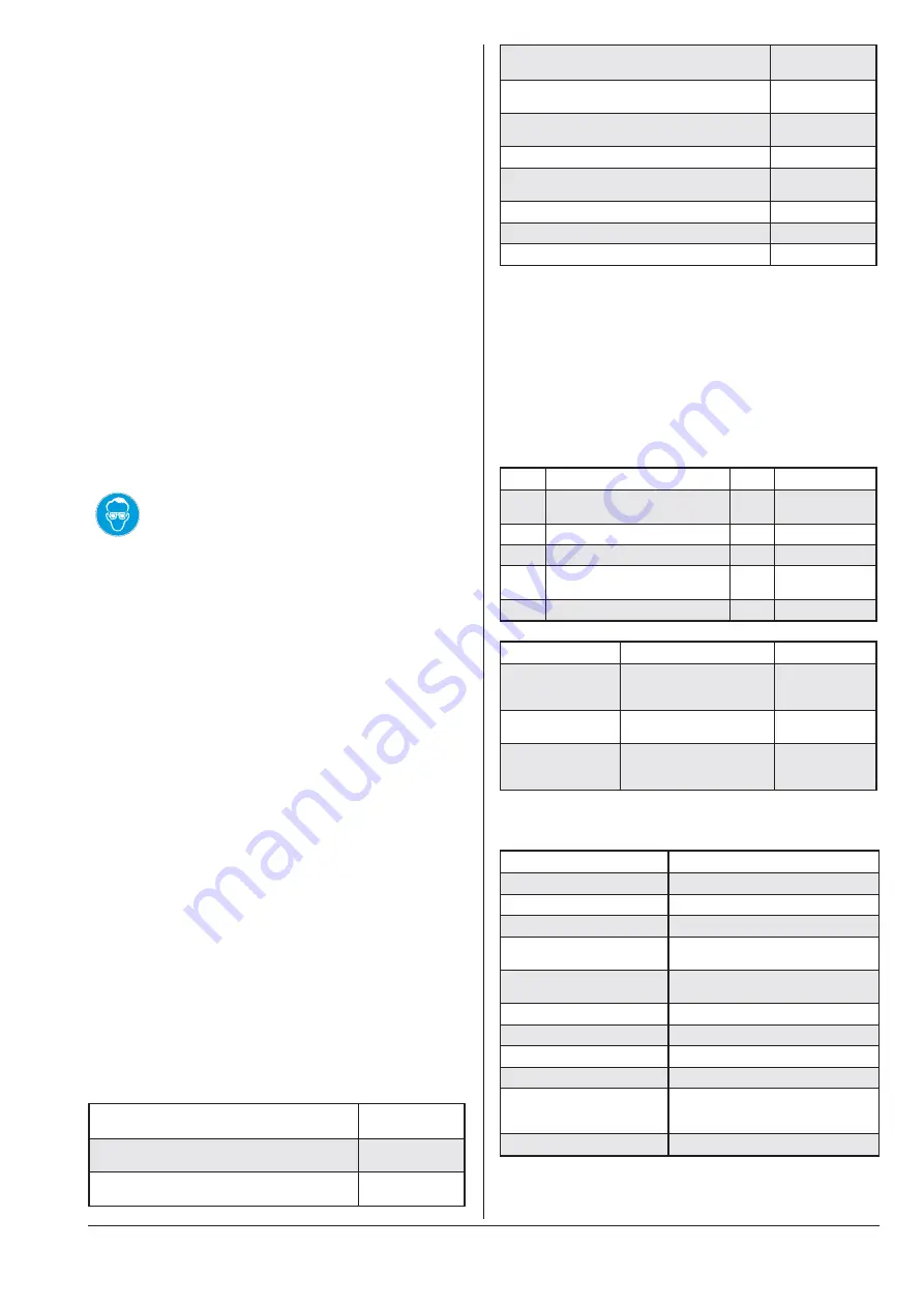
Technical Data
Nominal suction capacity
(50Hz/60Hz)
m³/h
16 / 19
Ultimate pressure
hPa (=mbar)
abs.
20
Motor nominal rating
(50Hz/60Hz)
kW
0.55
Motor nominal speed
(50Hz/60Hz)
min
–1
3000 / 3600
Sound pressure level
(EN ISO 2151) (50Hz/60Hz)
dB (A)
60 / 64
Operating temperature
(50Hz/60Hz)
°C
82 / 92
Ambient temperature range
°C
0 ... 40
Ambient pressure
Atmospheric
pressure
Oil quantity
l
0.3
Oil furnished ex-works
VSL 068
Weight approx. (50Hz/60Hz)
kg
~19
Spare Parts / Spare Parts Kits
The exclusive use of genuine spare parts and consumables is a pre-
requisite for the proper function of the vacuum pump and for the
granting of warranty, guarantee or goodwill.
Find the list of Busch companies all over the world (by the time of the
publication of these operating and maintenance instructions) on
Ú
page 8 (rear cover page).
Find the up-to-date list of Busch companies and agencies all over the
world on the internet at www.busch-vacuum.com.
Pos.
Part
Qty
Part no.
—
Vacuum pump, complete
090.116.700
0
1113 148 917
125
Filter spring
1
0947 000 719
261
Screen
1
0534 000 056
440
Gas ballast, complete
090.116.513
1
0916 106 678
—
Oil level switch 090.116.701
1
0652 149 308
Spare parts kit
Description
Part no.
Service kit
consisting of exhaust
filter and pertinent seals
090.116.512
0992 146 818
Set of
seals/gaskets
consisting of all necessary
seals
0990 146 817
Overhaul kit
consisting of seal set and
all wearing parts
090.116.511
0993 146 816
Oil
Denomination
VSL 068
ISO-VG
68
Base
PAO
Density [g/cm³]
0.83
Kinematic viscosity at 40 °C
[mm²/s]
68
Kinematic viscosity at 100 °C
[mm²/s]
10
Flashpoint [°C]
240
Pourpoint [°C]
–55
Part no. 1 l packaging
0831 131 846
Part no. 5 l packaging
0831 131 847
Remark
Food applications (NSF H1);
VEMAG-part no. 1l-packaging:
052.001.029
Filling quantity, approx. [l]
0.3
KC 0016 D VEMAG
0870146800 / 100111
page 2
Summary of Contents for HP10E
Page 8: ......
Page 10: ...HP10E HP12E HP15E HP20E Dairy design 0 Foreword 0 2 VEMAG 2013...
Page 26: ...HP10E HP12E HP15E HP20E Dairy design 3 Installation and commissioning 3 6 VEMAG 2013...
Page 34: ...HP10E HP12E HP15E HP20E Dairy design 4 Setting up 4 8 VEMAG 2013...
Page 38: ...HP10E HP12E HP15E HP20E Dairy design 5 Operation 5 4 VEMAG 2013...
Page 52: ...HP10E HP12E HP15E HP20E Dairy design 6 Graphical control 6 14 VEMAG 2013 Mode group Mode View...
Page 56: ...HP10E HP12E HP15E HP20E Dairy design 6 Graphical control 6 18 VEMAG 2013...
Page 58: ...HP10E HP12E HP15E HP20E Dairy design 6 Graphical control 6 20 VEMAG 2013...
Page 60: ...HP10E HP12E HP15E HP20E Dairy design 6 Graphical control 6 22 VEMAG 2013...
Page 97: ...HP10E HP12E HP15E HP20E Dairy design 6 Graphical control 6 59 VEMAG 2013...
Page 100: ...HP10E HP12E HP15E HP20E Dairy design 6 Graphical control 6 62 VEMAG 2013...


