21
106309-03 - 4/19
IV. Venting
A. General Guidelines (continued)
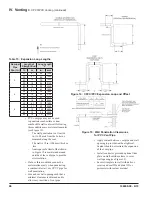
Figure 8: Direct Vent - Sidewall Snorkel Terminations
Figure 9: Direct Vent - Sidewall Low Profile Termination
ii.
Vertical Roof Venting: Use coupling on vent
and two 90° elbows turned downwards for
combustion air as shown in Figure 10 and
Figure 11.
b. Maintain correct clearance and orientation
between vent and combustion air terminals.
i.
Space centerlines of vent and combustion air
terminals minimum 12 in. (300 mm) apart.
36 in. (915 mm) spacing is recommended.
ii.
If possible, locate vent and combustion
air terminals on the same wall to prevent
nuisance shutdowns. If not, boiler may
be installed with roof vent terminal and
sidewall combustion air terminal.
iii.
When installed on the same wall, locate
vent terminal at same height or higher than
combustion air terminal.
c. Locate bottom of vent and combustion air
terminals at least 12 in. (300 mm) [18 in.
(460 mm) in Canada] above the normal snow line
and at least 12 in. (300 mm) above grade level.
d. Locate vent and combustion air terminals at
least 12 in. (300 mm) from any door, window, or
gravity inlet into the building.
e. Do not install vent terminal directly above
windows or doors.
Summary of Contents for Phantom-X Series
Page 49: ...49 106309 03 4 19 VI Water Piping and Trim continued Figure 28 Near Boiler Piping Heating Only...
Page 63: ...63 106309 03 4 19 VIII Electrical continued Figure 40 Ladder Diagram...
Page 64: ...64 106309 03 4 19 VIII Electrical continued Figure 41 Wiring Connections Diagram 2...
Page 73: ...73 106309 03 4 19 IX System Start up continued Figure 47 Operating Instructions...
Page 124: ...124 106309 03 4 19 XIII Service Parts continued...
Page 130: ...130 106309 03 4 19 XIII Service Parts continued...
Page 133: ...133 106309 03 4 19 XIII Service Parts continued 10A 10B 10C 10D 10G...
Page 139: ...139 106309 03 4 19...


