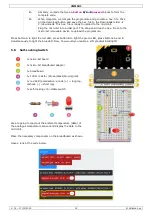
VMM501
V. 01 – 17/01/2019
16
©Velleman nv
1.
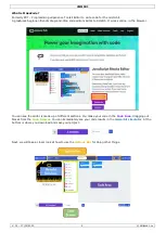
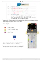
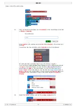
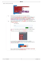
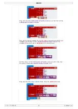
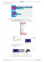
Drag and drop the code blocks to form the code as shown.
You can find the
set pin P0 to emit edge events
and
set pull P0 to up
blocks in
Pins
More
in the Code Drawer. You can find the
on event
from MICROBIT…EVT_FALL/RISE
blocks in
Control
in the Code
Drawer.
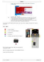
2.
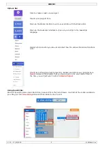
Set the events type on
edge
. Set the pull pin to
P0
and to
up
.
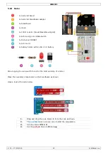
3.
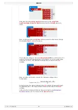
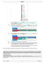
Now, make a fall event block. Drag and drop the
on event from
MICROBIT…EVT°FALL
block below the
on start
block. Click on the first
arrow and select the
MICROBIT_ID_IO_P0
option in the pull-down menu.
Click on the second arrow and select the
MICROBIT_PIN_EVENT_FALL
option in the pull-down menu.
Drag and drop the
digital write pin P0 to 0
block into the event block.
Set pin P0 to P2 and set 0 to 1. You can find the
digital write pin P0 to 0
block in
Pins
in the Code Drawer.
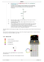
4.
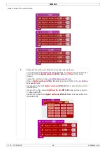
Do the same for the second event block. Instead, click on the second arrow
and select the
MICROBIT_PIN_EVENT_RISE
option in the pull-down
menu. Also, set pin P0 to P2 of the
digital write pin P0 to 0
block and set
the value to 0.
5.
When complete, we compile the programme and generate a hex. file. Click
on the download button and save the hex. file to the Downloads folder
C:\downloads. This hex. file is ready to upload to the micro:bit.
Plug the micro:bit into a USB port. The, drag and drop the hex. file onto the
micro:bit removable device to upload the programme.
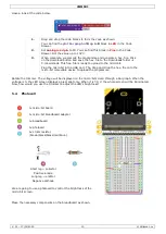
Press down the self-locking switch and the LED will switch on. Press again to switch off the LED. Now, how
would you control the micro:bit display with this self-locking switch?
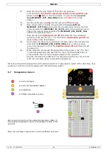
5.7
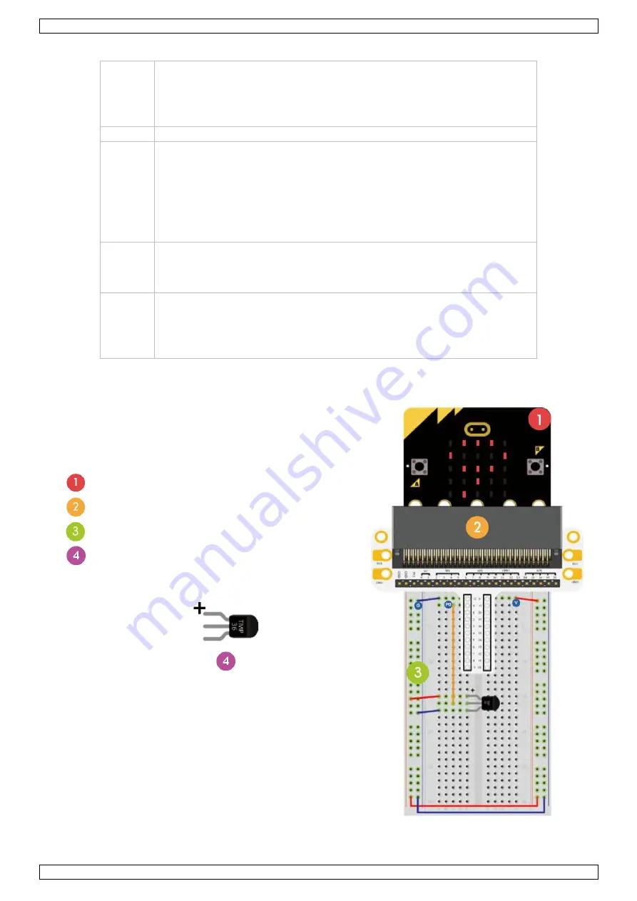
Temperature Sensor
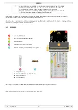
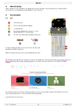
1x micro:bit board
1x micro:bit breadboard adapter
1x breadboard
1x TMP36 temperature sensor
We are going to read out the ambient temperature (data) of
the analogue temperature sensor and display the data to the
micro:bit.
Place the necessary components on the breadboard as shown.

