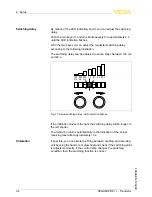
P
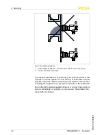
olarisation direction
T
he emitting unit emits electromagnetic waves
.
T
he polarisation plane
is the direction of the electrical wave component
.
I
ts position is marked
on the instrument hexagon by polarisation markings
.
F
or a reliable function
,
the emitting and receiving unit must be installed
in the same polarisation direction
.
I
f several instrument pairs are installed in a vessel
,
the instrument pairs
can be coded by di
ff
erent polarisation positions to avoid that they
in
fl
uence one another
.
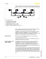
2
1
1
2
F
ig
.
13
:
O
rientation according to the polarisation direction
1
P
olarisation marking on top
2
P
olarisation marking lateral
I
n tight mounting spaces or spaces subject to high temperatures
,
the
signal of
VEGAMIP
61
can be guided via a de
fl
ector
.
F
or this you can
use a metal plate or an angled antenna extension on the side of the
emitting unit
.
I
n products with low dielectric value
,
we recommend
using an instrument version with antenna extension because it
focusses the signal optimally and has no signal loss
.
W
ith instrument
versions with detachable horn antenna
,
the antenna extension can be
retro
fi
tted
.
S
pecial mounting op
-
tions
VEGAMIP R
61
• -
T
ransistor
21
4
M
ounting
40694
-
EN
-
120228

