N
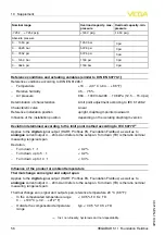
ominal range
O
verload capacity
,
max
.
pressure
O
verload capacity
,
min
.
pressure
-
7
.
252
…
+
7
.
252
psig
+
145
.
0
psig
-
14
.
50
psig
A
bsolute pressure
0
…
14
.
50
psi
145
.
0
bar
0
psi
0
…
36
.
26
bar
507
.
6
psi
0
psi
0
…
72
.
52
psi
507
.
6
psi
0
psi
0
…
145
.
0
bar
1160
psi
0
psi
0
…
362
.
6
psi
1160
bar
0
psi
R
eference conditions and actuating variables
(
similar to
DIN EN
60770
-
1
)
R
eference conditions according to
DIN EN
61298
-
1
-
T
emperature
+
18
…
+
30
°
C
(
+
64
…
+
86
°
F
)
-
R
elative humidity
45
…
75
%
-
A
ir pressure
860
…
1060
mbar
/
86
…
106
k
P
a
(
12
.
5
…
15
.
4
psi
)
D
etermination of characteristics
L
imit point adjustment according to
IEC
61298
-
2
C
haracterstic curve
L
inear
R
eference installation position
upright
,
diaphragm points downward
I
n
fl
uence of the installation position
depending on the isolating diaphragm version
D
eviation determined according to the limit point method according to
IEC
60770
12
)
A
pplies to the
digital
signal output
(
HART
,
P
ro
fi
bus
PA
,
F
oundation
F
ieldbus
)
as well as to
analogue
current output
4
…
20
m
A
and refers to the set span
.
T
urn down
(
TD
)
is the ratio nominal
measuring range
/
set span
.
D
eviation
-
T
urn down
1
:
1
<
0
.
2
%
-
T
urn down up to
5
:
1
<
0
.
2
%
-
T
urn down up to
10
:
1
<
0
.
3
%
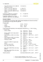
I
n
fl
uence of the product or ambient temperature
T
hermal change zero signal and output span
A
pplies to the
digital
signal output
(
HART
,
P
ro
fi
bus
PA
,
F
oundation
F
ieldbus
)
as well as to
analogue
current output
4
…
20
m
A
and refers to the set span
.
T
urn down
(
TD
)
is the ratio nominal
measuring range
/
set span
.
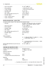
T
hermal change zero signal and output span
,
reference temperature
20
°
C
(
68
°
F
):
-
I
n the compensated temperature range
0
…
+
100
°
C
(
+
32
…
+
212
°
F
)
<
0
.
05
%
/
10
K
x
TD
-
O
utside the compensated temperature
range
typ
.
<
0
.
05
%
/
10
K
x
TD
12
)
I
ncl
.
non
-
linearity
,
hysteresis and non
-
repeatability
.
56
VEGABAR
51
•
F
oundation
F
ieldbus
10
S
upplement
36715
-
EN
-
110629


