I²C
3
4
5
1
2
Display
Typ:
1
2
5 6 7 8
Bus
Sim.
F
ig
.
9
:
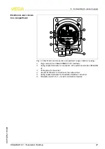
E
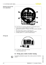
lectronics and connection compartment
,
single chamber housing
1
P
lug connector for
VEGACONNECT
(
I
²
C
interface
)
2
S
pring
-
loaded terminals for connection of the external indication
VEGADIS
61
3
G
round terminal for connection of the cable screen
4
S
pring
-
loaded terminals for
F
oundation
F
ieldbus connection
5
S
imulation switch
(
"
on
" =
mode for simulation release
)
I2C
Display
1
1
2
5
6
7
8
F
ig
.
10
:
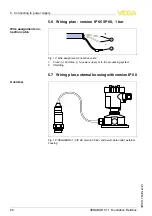
W
iring plan
,
single chamber housing
1
V
oltage supply
/
S
ignal output
5
.
4
W
iring plan
,
double chamber housing
T
he following illustrations apply to the non
-
E
x as well as to the
E
x
-
ia
version
.
E
lectronics and connec
-
tion compartment
W
iring plan
22
VEGABAR
51
•
F
oundation
F
ieldbus
5
C
onnecting to power supply
36715
-
EN
-
110629

