background image

FX8x Series User Manual 


Page 23 of 50 

Ports Settings 


4.  Select the necessary port by pressing 

|Up| 

and 

|Down|

5.  To switch the selected port ON/OFF, press 

|Shift/Enter|

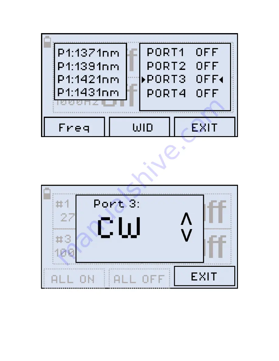
6.  To set up the selected port frequency, press 

|F1| (Freq)

. The screen shown below 

appears: 

Setting up a separate port 


7.  Select the necessary frequency by pressing 

|Up| 

and 

|Down|

8.  To turn on the WaveID function for the selected port, press 

|F2| (WID)

. Note that turning 

on the WaveID function automatically selects the Continuous Wave frequency for this 

port. 

Summary of Contents for FX8 Series

Page 1: ......

Page 2: ...OPM measurement 15 6 2 1 Setting Power Reference Level 17 7 0 Optical Light Source 20 7 1 Optical Light Source for FX86 22 7 2 Optical Light Source for FX87 25 8 0 Visual Fault Locator VFL 28 9 0 Opt...

Page 3: ...FX8x Series User Manual Page 3 of 50 15 0 Product Specifications 48 16 0 Certifications and Declarations 49 17 0 About VeEX 50...

Page 4: ...in other countries All trademarks or registered trademarks are the property of their respective companies No part of this document may be reproduced or transmitted electronically or otherwise without...

Page 5: ...situation Make sure that optical sources are inactive before connecting fiber to the test set to avoid skin or eye damage or damage to the unit It is recommended to Deactivate the laser before connect...

Page 6: ...tdoors and backlight for indoor or low light conditions Handheld lightweight rugged design Protective rubber boot with tilt bail stand Splash and dust resistant design Non volatile storage for saved t...

Page 7: ...Universal connector adapters Optical Light Source OLS Dual Tri and Quad wavelength options Single mode 1310 1490 1550 and 1625nm Quad CWDM per ITU T G 694 2 grid Tunable DWDM per ITU T G 694 1 grid Mo...

Page 8: ...i directional OLTS Bi directional OLTS ORL CWDM OLS DWDM TLS Fiber Type SM MM SM SM SM SM SM OPM OPM with LS OPM with DWDM Light Source Up to 4 fixed Up to 4 fixed Up to 4 fixed 4 fixed per G 694 2 C...

Page 9: ...X82 test unit is shown below FX82 front view 4 1 1 Optical ports Optical ports up to 4 are located at the top of the device 4 1 2 Front buttons Power Turn device ON OFF Press and hold the button for 3...

Page 10: ...er Mode Turn backlight ON OFF F1 F2 F3 Context defined the function indicated at the screen bottom 4 1 4 Service Ports The micro USB port located on the left side of the device is used for charging an...

Page 11: ...he test unit connect the AC DC adaptor supplied with the unit to the micro USB service port located on the left side of the device The battery charging time depends on the battery condition and ambien...

Page 12: ...parameter currently selected and available to edit will flash Instrument Setting screen 3 Press Up and Down to select the parameter to edit 4 Press MODE to select the field to edit then change the va...

Page 13: ...alues and reference values will be lost These values must be reset Also ZERO level operation must be performed again For more information see Sections 6 1 Setting ZERO Level and 6 2 1 Setting Power Re...

Page 14: ...l level CW 270 330 1000 or 2000 Hz between the wavelength range of 850 1650 nm Select a calibrated wavelength that matches the incoming source wavelength For best results wait 15 minutes after the dev...

Page 15: ...iefly on the display Setting the ZERO level The test unit is now ready for measurements 6 2 OPM measurement To measure the optical power in a fiber insert the test fiber on the OPM test port and press...

Page 16: ...M measurement The fiber under test must have only one wavelength If there are several wavelengths the measurement results will NOT be valid To change the wavelength press the F1 button WAVE The result...

Page 17: ...velength and then press the F1 EXIT button If the fiber under test carries a signal with WaveID details select AUTO Then the device FX82 FX84 or FX85 determines the wavelength automatically If the AUT...

Page 18: ...as the reference level Select REF FIX with the cursor and press the Shift Enter button The value onscreen then changes to dB The current reference level value is shown on the second row to the right...

Page 19: ...eturn to normal absolute measurement REF command finely adjusts the current reference level Press the Up and Down buttons to change the reference level by 0 01 To set the adjusted level as reference p...

Page 20: ...tionality FX86 and FX87 employ CWDM and DWDM technologies respectively and their Optical Light Source menus are different see Sections 7 1 Optical Light Source for FX86 and 7 2 Optical Light Source fo...

Page 21: ...unit then shows the Optical Light Source menu Setting wavelength and mode for Optical Light Source 3 To select the necessary wavelength press Up and Down 4 To set the mode press F1 MOD repeatedly You...

Page 22: ...the Optical Light Source for FX86 1 Switch on FX86 the initial screen is shown Note that the port frequencies are different and may need to be changed see below Initial Settings screen for FX86 Optica...

Page 23: ...t Enter 6 To set up the selected port frequency press F1 Freq The screen shown below appears Setting up a separate port 7 Select the necessary frequency by pressing Up and Down 8 To turn on the WaveID...

Page 24: ...FX8x Series User Manual Page 24 of 50 9 To finalize the settings press F3 EXIT Every port can have separate settings Now the ports are emitting not emitting laser light according to the settings...

Page 25: ...e first set the Optical Light Source parameters and then connect the fiber under test FUT or vice versa The order does not matter The optical port used for the DWDM Light Source is always located on t...

Page 26: ...set 3 To set the Channel press F2 CHANNEL Then select the Channel by pressing Up and Down To confirm the setting press Shift Enter Selecting wavelength for DWDM Light Source 4 To set the mode press th...

Page 27: ...FX8x Series User Manual Page 27 of 50 DWDM Light Source is set...

Page 28: ...82 FX83 and FX84 can be equipped with a Visual Fault Locator VFL To test a fiber line for continuity 1 Connect the fiber to the VFL port 2 Press the MODE button until get the VFL mode appears see the...

Page 29: ...4 To modulate the light 1 or 2 Hz press F2 1Hz or F3 2Hz respectively The pressed button then changes to CW and you can press it to return to continuous light see an example below VFL testing modulate...

Page 30: ...k to the optical port and via the optical splitter it is directed to the Optical Power Meter The incoming signal level is compared to the calibration values and the Return Loss is shown onscreen To en...

Page 31: ...y pressing Up and Down Confirm your selection by pressing Shift Enter The screen like the one shown below appears ORL wavelength selected Make sure the optical port is tightly capped during calibratio...

Page 32: ...F3 REF_C then set the 14 00 value by pressing Up and Down Setting ORL reference value 6 After setting the 14 00 value press Shift Enter The reference value is then saved to the device memory 7 Discon...

Page 33: ...FUT to the optical port The measurement result is then shown onscreen see an example below ORL measurement result To save the current measurement result press Shift Enter Up The Saved notification app...

Page 34: ...ns to exchange voice information over the fiber under test FUT To use this functionality 1 Press the MODE button until the VOICE mode appears at the upper left corner of the display Entering VOICE mod...

Page 35: ...ncoming call will not get through 3 The technician on the other end of the FUT gets the Incoming Call notification on their unit Receiving a call in VOICE mode To accept a call the technician on the o...

Page 36: ...t results press the MODE button until the Read mode appears at the upper left corner of the display and the results are shown Viewing Measurement Results Read mode The FX82 can be optionally equipped...

Page 37: ...NT until the cursor starts flashing in the INDEX field or in the COMMENT field 3 Then use the Up and Down buttons to position the cursor in the set of symbols The active symbol then gets flashing Use...

Page 38: ...with the current note Press the Shift Enter Up button combination Save The Saved notification is then briefly shown onscreen and current measurement results with the current note are saved in the devi...

Page 39: ...or wired transfer For a PC to work with the FX82 device install the USB driver 1 Plug in the FX82 device to the PC via the supplied micro USB cable Check the Windows Device Manager to see the FX82 ite...

Page 40: ...o the previously saved downloaded driver and click Next The driver installation starts After the installation is complete a window appears indicating the driver has been installed successfully see bel...

Page 41: ...B cable provided The FX Series devices window appears example shown below with the device and its serial number recognized by the program FX82 is connected to PC in LTSync its serial number is recogni...

Page 42: ...eriod checkbox The Filter box appears see below Filtering measurement results by time To delete a row s of results select the checkbox next to the row s and then click the Delete row button To move a...

Page 43: ...es with the standard Bluetooth pairing procedure If paired the FX82 should appear in the Bluetooth Other Devices list in the Windows X Device Manager See the icon example below taken in Win10 FX 82 li...

Page 44: ...device in the drop down list After the FX82 and PC are connected the Bluetooth sign inverts its colors see below FX82 and PC connected shows Bluetooth sign with inverted colors 5 To transfer measurem...

Page 45: ...tials in the resulting form Signing in to Fiberizer Cloud 2 Enter the user credentials in the resulting form Fiberizer Cloud Login screen To register for a Fiberizer Cloud account on the Cloud Storage...

Page 46: ...utton to upload the measurement LTSync creates a folder in the Fiberizer Cloud account named after the connected device for example FX82 7654321 to which it uploads the results The results saved in th...

Page 47: ...the customer elects to replace are returned to VeEX Inc by the customer along with proof of purchase within thirty 30 days of the request by the customer freight prepaid Additionally during the warran...

Page 48: ...FX8x Series User Manual Page 48 of 50 15 0 Product Specifications The most recent product specifications can be found on the VeEX web site at www veexinc com...

Page 49: ...rements of European Union and European Free Trade Association EFTA EN61010 1 For a copy of the CE Declaration of Conformity relating to VeEX products please contact VeEX customer service What is RoHS...

Page 50: ...all stages of network deployment maintenance and field service turn up and integrate service verification features across DSL fiber optics CATV DOCSIS mobile backhaul and fronthaul CPRI OBSAI next gen...

Reviews: