background image

OPERATION

10

Operation

Phone operation is mainly via the specific phone menus of the navigation system. The 
remote control buttons have the following functions:

OK

Confirmation of the selected menu items / 
activation of the button highlighted with the cursor in the menus

MENU

Return to navigation (Start Menu)

4

6

8

2

Control of the cursor / selection of menu points

+

-

Adjustment of phone volume during telephoning

1

The two steps of highlighting a menu entry with the cursor followed by pressing the 

OK

 button on the remote control are referred to in the sections below as "selecting" a 

function / option.

Putting into operation

There must be a suitable mobile phone in the holder in order to use the hands-free unit.

Switching on

The hands-free unit is automatically switched on with the ignition.

1

On some mobile phones (see associated operating instructions), a special symbol (car 

symbol) or a hands-free message is displayed when the phone is inserted in the holder of 
the hands-free unit.

1. Switch on the ignition.

The navigation system starts.

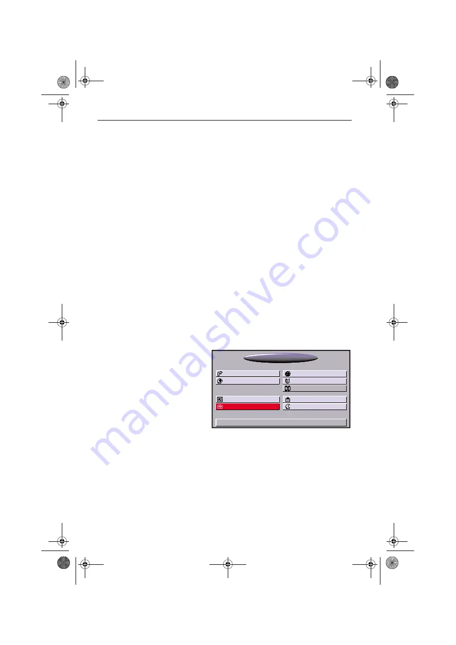
2. Select "Telephone" option.

When the mobile phone is ready for operation, the phone menu appears. 
If the phone is not inserted in the holder or is not ready for operation, corresponding 
information is displayed.
In this case, check that the phone is correctly inserted in the holder, that it is switched 
on, and that the PIN number has been entered.

9:17

TMC

01.05.2002

Map

Stand-by

Address book
Travel info

Settings

Navigation

Emergency

Trip computer

Start Menu

Telephone

MG3000_Color_en.book  Seite 10  Mittwoch, 14. August 2002  8:15 08

Summary of Contents for MG 3000 -

Page 1: ...iksaanwijzing en inbouwhandleiding Istruzioni d uso e d installazione Instrucciones de manejo y de montaje Owner s manual and mounting instruction Mode d emploi et manuel d installation Bedienungs und...

Page 2: ...2 2 MGC 3000 XX MGA 3000 C 7 5 6 9 8 Operating Software MO XXXX 4 not a Siemens VDO accessory 3 1 MGE 3000 MG3000_Color_de book Seite 2 Dienstag 2 Juli 2002 11 02 11...

Page 3: ...5...

Page 4: ...tung Seite 71 Afbeeldingen Pagina 2 4 Gebruiksaanwijzing Pagina 79 Inbouwhandleiding Pagina 95 Figure pag 2 4 Istruzioni per l uso pag 103 Istruzioni per il montaggio pag 119 Ilustraciones P gina 2 4...

Page 5: ...alling 13 Dialling via numeric buttons 13 Call lists 14 Calls from the navigation system address book 14 Phone Book 14 Retrieving an entry from the phone book 15 Deleting an entry 15 New entry 15 SMS...

Page 6: ...ake phone calls while driving Observe local regulations relating to making phone calls in the vehicle A Switch off the telephone at petrol stations chemical plants fuel depots or similar facili ties o...

Page 7: ...5400 C M S 35 and SL 42 45 only The mobile phone is not recharged via the hands free unit in GSM modem mode e g when sending receiving faxes Special features with Nokia 6210 6310 7110mobile phones Nok...

Page 8: ...to use the hands free unit Switching on The hands free unit is automatically switched on with the ignition 1 On some mobile phones see associated operating instructions a special symbol car symbol or...

Page 9: ...ed The monitor and the remote control are switched off immediately Phone Menu After selecting the Phone function in the start menu the Phone menu is displayed The main functions of the phone are contr...

Page 10: ...ed Field strength display The strength of the phone reception signal is shown by the number of black solid rectangles on the left side in the Phone menu The field strength can also be indicated in the...

Page 11: ...he virtual keypad After highlight ing a button with the cursor and then pressing the OK button the digit is shown in the display zone above yellow Wrong entries can be deleted using the C button 1 Aft...

Page 12: ...g the OK button the Phone menu is displayed again the selected call number appears in the yellow display zone By pressing the green handset button the connection can be initiated Calls from the naviga...

Page 13: ...d in Retrieving an entry from the phone book After selecting the desired entry a safety prompt is displayed in order to prevent the inadvertent deletion of an entry 3 Select the Delete option in order...

Page 14: ...s When new SMS messages are received the message New SMS Read now is indicated on the display 1 This message is also shown when the system has been switched to stand by 1 Select Yes if you would like...

Page 15: ...m or top of the message Below the display window for the text the sender s call number is displayed only if caller identification is supported The function buttons below have the following purposes Ed...

Page 16: ...n the phone menu 2 Select the SMS templates option in the list of functions A ready made text menu is displayed in the SMS templates menu You can view and select the available standard texts via List...

Page 17: ...the call number is automatically adopted in the Send message menu Versions This information is important for Customer Service please have this information at hand during calls to Customer Service Cus...

Page 18: ...al information may be displayed e g as follows 2 Highlight the phone symbol with the 4 or 6 cursor buttons 3 Press the OK button The connection is established Or 4 When the phone symbol is highlighted...

Page 19: ...all up the Emergency menu see navigation system operating instructions 2 Select For emergency call 3 Confirm the subsequent message with OK within 5 seconds The connection is established 1 For selecti...

Page 20: ...holder and switch it off Remove and reinsert the battery in the mobile phone Put the phone back into the holder The other person s voice cannot be heard during phone calls Loudspeaker not connected or...

Page 21: ...e loudspeaker 25 Installing the microphone 26 Installing the phone holder 26 Make electrical connections 27 Initial operation 28 Loading software updates 28 Check the connections 28 Check the function...

Page 22: ...marked for example by labels A A A A Do not use test lamps to test the voltage since excessively high currents can damage destroy electronic components A A A A Do not use any pinch or cut connectors S...

Page 23: ...o a vehicle loudspeaker e g using adapter cable MA 1300 the hands free unit must not be connected to the same vehicle loud speaker via the integrated loudspeaker crossover The control unit features a...

Page 24: ...and secure the adhesive pad to the back of the microphone 3 Completely remove the protective film position the microphone at the required loca tion and press it firmly into place Installing the phone...

Page 25: ...speaker socket on the front of the control unit 4 Insert the microphone jack into the correspondingly labelled socket on the front of the control unit 5 Insert the 15 pin plug of the telephone holder...

Page 26: ...or the antenna connection on the telephone The navigation system starts 3 In the Start Menu select the option Phone see navigation system operating instructions Phone not ready should then be displaye...

Page 27: ...e of the control unit with the cable tie at the lug in order to prevent the jack from being pulled out 2 Secure all components of the hands free unit in the vehicle 3 Refit all panels etc that have be...

Page 28: ...iksaanwijzing en inbouwhandleiding Istruzioni d uso e d installazione Instrucciones de manejo y de montaje Owner s manual and mounting instruction Mode d emploi et manuel d installation Bedienungs und...

Reviews: