


Series 655
INSTALLATION
979645EA
Edition 23.09.2019
69/112
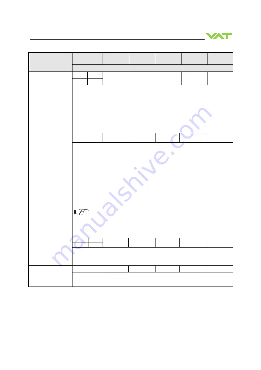
Command
Service Code
Class ID
Instance ID
Attribute ID
Service
data length
(number of bytes)
Service
data field
Description
GAIN
Set
16
49
1 Pressure
3 Position
14
4 float
X
Get
14
X:
Gain, max. value is 3.2767, data type is floating point
This command selects the gain for PRESSURE/POSITION and allows for scaling.
Default value is 1.0
Example:
Gain
X (hex)
Resulting range
0.1
3D CC CC CC
0 … 1000
1.0
3F 80 00 00
0 ... 10000
3.2767
40 51 B5 73
0 … 32767
SENSOR MODE
Set
16
49
1
101
1
X
Get
14
X: 0 = no sensor
1 = sensor 1
2 = sensor 1 high, sensor 2 low, crossover fade
7 = sensor 1 high, sensor 2 low, crossover target pressure
9 = sensor 1 high, sensor 2 low, crossover switch point
3 = sensor 2
4 = sensor 2 high, sensor 1 low, crossover fade
8 = sensor 2 high, sensor 1 low, crossover target pressure
10 = sensor 2 high, sensor 1 low, crossover switch point
2 sensor operation are possible with 2 sensor hardware [950..-...Q -....] only.
For applications where the high range sensor is used for monitoring purpose
only, select sensor operation modes 1 or 3 for pressure control with low range
sensor and read high range sensor from SENSOR 1 READING resp. SENSOR
2 READING.
ZERO CONTROL
Set
16
49
1
102
1
X
Get
14
X:
0
Disable
1
Enable
In case ZERO CONTROL is disabled ZERO ADJUST does not work.
ZERO ADJUST
75
49
1
-
0
-
This service initiates ZERO ADJUST.
Note: Refer to «Zero adjust» for correct zero procedure.
Note: Pressure Reading and Offset Values of Sensor 1 and Sensor 2 are in Pressure Controller Object (Class ID 100)


