Vasco T350 Installation Manual Download Page 16

14MOUNTING SWITCHES


The position switch is registered with the ventilation unit at the factory. 

If all air and electrical connections have been made, the plug may be inserted 
into the mains socket. 

After 1 minute and 30 seconds, the fans start up briefly (about 4 seconds). 


Then you have 10 minutes to set the air volume and to connect additional 
optional position switches. 


Adjusting the air volume: 

Press the button for position 3 for at least 3 seconds and release it when the 
LED in the centre of the switch gives a series of light signals. These indicate the 
air quantity set. In the factory, the LED lights up orange once. 


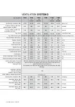
Indication LED on switch 

T350 

T500 

1x green 

230 m³/h 

350 m³/h 

2x green 

250 m³/h 

375 m³/h 

1x orange (standard) 

270 m³/h 

400 m³/h 

2x orange 

290 m³/h 

425 m³/h 

3x orange 

310 m³/h 

450 m³/h 

1x red 

330 m³/h 

475 m³/h 

2x red 

350 m³/h 

500 m³/h 


Reducing the air volume: 
Press the button of position 1 once. The LED indication will change according 
to the table. By repeatedly pressing the button of position 1 at 1 second 
intervals, the air volume is further reduced. 


Increasing the air volume: 
Press the button of position 2 once. The LED indication will change according to 
the table. By repeatedly pressing the button at 1 second intervals, the 
of position 2, the air volume is further increased. 


Press the button of position 3 for at least 3 sec. to confirm the change. If the RF 

switch remains untouched for one minute, the changes are automatically 
saved. 

COMMISSIONING AND 

ADJUSTMENT 

Summary of Contents for T350

Page 1: ...INSTALLATION MANUAL VENTILATION UNIT VASCO T350 T500 SYSTEM D...

Page 2: ...CONDITIONS 05 ASSEMBLY PREPARATIONS 05 ELECTRIC PRE HEATING ELEMENT T350 T500 07 MOUNTING THE VENTILATION UNIT CONDENSATION DRAIN 08 AIR DUCT CONNECTIONS 09 MOUNTING SWITCHES 10 COMMISSIONING AND ADJ...

Page 3: ...nt of a defect contact a professional installer and have repairs carried out only by qualified personnel This appliance is not intended for use by persons including children with reduced physical sens...

Page 4: ...ventilation unit has been installed and all components have been assembled Vasco is not liable for any damage caused by not observing the safety instructions or not following the instructions in the u...

Page 5: ...racket ventilation unit Suspension brackets wireless mode switch Installation manual User Manual 2 bumpers supplied separately 2 Galva sockets below unit connection INSTALLATION MANUAL FOR THE INSTALL...

Page 6: ...e wall 16 Depth 560 110 centre distance 520 110 180 Mains cable 230 VAC Antenna RF Cable grommet wired 3 position switch or cable 0 10V control both cables to be provided by the installer 764 Sizes in...

Page 7: ...age as well as the regulations in this manual The following facilities must be available in the room air duct connections 230V 10 single phase 50Hz socket provision for the condensation drain no const...

Page 8: ...ackets of the ventilation unit have to be fixed on the right side as shown in the following figures STANDARD CONFIGURATION RIGHT REVERSED CONFIGURATION LEFT Stick the protective caps on the ventilatio...

Page 9: ...F THE PRE HEATING ELEMENT Attention The electric pre heating element must be in place before the ventilation unit is fixed to the wall Attach the door panel to the connection from outside The electric...

Page 10: ...free and airtight manner A siphon is part of this drainage system and must be provided on site separately We advise to glue the connection to the ventilation unit or to connect it airtight by using a...

Page 11: ...The main air ducts should have an internal diameter of 170 mm or 180 mm Connection residential side Vasco recommends using the Vasco Easyflow air duct system External connection The air ducts of the...

Page 12: ...OUNTING RF SWITCH Always install the RF position switch in an easily accessible location Step 1 Loosen the knobs and the electronics module to free the base plate for wall mounting Step 2 Draw screw h...

Page 13: ...230V supply voltage to the connectors Step 2 Screw the base plate onto the wall Step 5 Place the cover back on the switch Step 3 Open the cover on the base plate to reveal the electrical connections...

Page 14: ...purpose in the ventilation unit Finally connect the cable to terminal X9 Connection 3 position switch according to the following diagram 3 position switch or 3 fold switching module Intended grommets...

Page 15: ...signal the cover on the ventilation unit must be opened in a correct manner so that the circuit board can be reached This method can be found in the chapter on the electric pre heating element Next a...

Page 16: ...n switch T350 T500 1x green 230 m h 350 m h 2x green 250 m h 375 m h 1x orange standard 270 m h 400 m h 2x orange 290 m h 425 m h 3x orange 310 m h 450 m h 1x red 330 m h 475 m h 2x red 350 m h 500 m...

Page 17: ...cted Activating and deactivating optional CO2 RF switch 11VE20013 Sign up Unplug the ventilation unit and plug it back in After this the ventilation unit will search for new switches for 10 minutes Af...

Page 18: ...ht up green twice and a LED will light up on the right indicating the respective position of the RH RF switch is located Tip You can connect one switch to a maximum of 3 units Momentarily de energise...

Page 19: ...ter trays from the unit Pull the strap of the heat exchanger never remove it If necessary clean the heat exchanger by wiping the four surfaces with a damp cloth Do not use aggressive or solvent cleani...

Page 20: ...sen the screw on the fan module Tilt the fan module by pulling the metal tab Pull the fan module out of the unit Do this for both fan modules Use a soft brush to clean the fans and sensors and a hoove...

Page 21: ...LEMENT CONNECTION X20 BLACK TEMPERATURE SENSOR OF THE HOUSE X21 BLACK TEMPERATURE SENSOR TO OUTSIDE X22 WHITE TEMPERATURE SENSOR FROM OUTSIDE X23 WHITE TEMPERATURE SENSOR TO THE HOUSE X25 DECORATIVE F...

Page 22: ...Ventilation unit runs at a higher speed than when it was first put into operation Hang the unit level Make sure that the condensation drain is properly connected To ensure correct operation the supply...

Page 23: ...that the cause is removed House not heated enough at least 16 C to ensure correct operation connected correctly see page 9 Channels connected correctly If the unit switches off again please contact y...

Page 24: ...VE 50358Filter setgreen 495x186x10mm 2 pcs T350 T500 11VE 50359Filter set F7 G4 481x186x20mm T350 T500 911VE 50400Heat exchanger T350 T500 1011VE 51101Fan 85W190 T350 11VE 51102Fan 170W190 T500 11 11V...

Page 25: ...ssional maintenance Defects resulting from use in an unsuitable environment No warranty will be given if the ventilation unit is used in these conditions For the return shipment of the defective parts...

Page 26: ...ic input power SPI 0 223 0 223 0 223 0 285 0 285 0 285 W m h Control factor 1 0 85 0 65 1 0 85 0 65 1 0 95 0 85 0 65 Maximum percentages of internal leakage 0 65 0 65 0 65 0 45 0 45 0 45 Maximum perce...

Page 27: ...g room living room office Bedroom 1 Bedroom 2 Bedroom 3 Bedroom 4 kitchen kitchen toilet washing station bathroom TOTAL AIR DEBATE CALCULATION SHEET VENTILATION local valve n supply design m h measure...

Page 28: ...Kruishoefstraat 50 B 3650 Dilsen T 32 0 89 79 04 11 F 32 0 89 79 05 00 info vasco e u www vasco eu...

Reviews: