background image

Please call for replacement parts or assistance: 

1-866-942-5362


VAS Furniture Mfg. Inc. 

Factory No. 33-10944 

Page # 3 

Parts List 


Please read completely through the instructions and verify that all 
parts listed are present before beginning assembly.  


A-Top Frame (1)                        


B- Shelf Frame (1)


C- Bottom Frame (1)


  D- Long Spine (1) 


  D1- Short Spine (1) 

EL- Left Side Leg (1)  

   ER- Right Side Leg (1)


F- Top Glass (1)   

G- Middle Shelf (1)  

H- Bottom Glass Shelf (1)  


I- Deluxe Plasma Bracket (1)   


   J- Mounting Frame (1)   


K- Monitor Bracket (2)   


     L- Safety Bar (1) 

Summary of Contents for XL-1

Page 1: ...arding assembly or if you are missing parts do not return this item to the Retailer Store Please call our customer service number and have your instructions and parts list ready to provide the model n...

Page 2: ...t a spacer Some televisions have a curved back or have recessed back This may require a longer Bolt along with a Spacer placed between the television and the Monitor Bracket Follow the diagrams upper...

Page 3: ...hrough the instructions and verify that all parts listed are present before beginning assembly A Top Frame 1 B Shelf Frame 1 C Bottom Frame 1 D Long Spine 1 D1 Short Spine 1 EL Left Side Leg 1 ER Righ...

Page 4: ...4 1 extra 8 1 extra 9 Concrete Anchor 10 Lag Bolt 11 Lag Bolt Washer 6 6 6 Open Wrench 1 Allen Wrench 1 Tipping Restraint Hardware Kit 1 Inside Plastic White Bag TV Mounting Kit M4 x 12 Bolt 4 M4 x 30...

Page 5: ...steps you don t need according to your option Option 1a Long Spine Steps 10 11 Swinging Mount DLX Plasma Bracket Option 1b Long Spine Steps 12 to 18 Swinging Mount Mounting Frame Option 2 Short Spine...

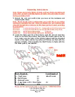
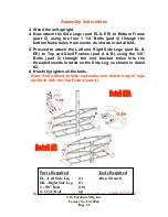
Page 6: ...nside As shown in detail 2A 5 Proceed to attach the Left and Right Side Legs part EL ER to Top and Shelf Frames part A B using the 5 8 Bolts part 2 through the end bracket holes into the threaded inse...

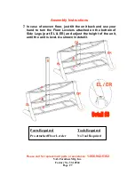
Page 7: ...sembly Instructions 7 In case of uneven floor just tilt the unit back and use your hand to turn the Floor Levelers attached on the bottom of Side Legs part EL ER and adjust the height of the unit unti...

Page 8: ...L ER into place As shown in detail 4 9 Place the Glass Shelf part F G H in place as shown in detail 4 Note Make sure that the Glass sits correctly and goes all the way into the grooves on the Spine an...

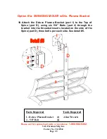
Page 9: ...MOUNT w Dlx Plasma Bracket 10 Attach the Deluxe Plasma Bracket part I to the Top of Spine part D using six 5 8 Bolts part 2 through the bracket into the threaded inserts located on the side of the Spi...

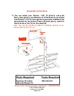
Page 10: ...all your Plasma LCD TV directly using the Bolts through the Lock Washers and Flat Washers provided with Plasma LCD TV through the proper holes of Metal Plate pre attached on the Deluxe Plasma Bracket...

Page 11: ...art J to the Deluxe Plasma Bracket part I using four 3 4 Bolts part 3 through the Flat Washer part 8 through the holes of Mounting Frame part J and Plasma Mounting Plate through the other Flat Washer...

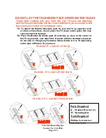
Page 12: ...he Monitor Brackets part K lean the TV up against a wall or other solid surface do not place the TV down on the glass this may cause permanent damage 14 Place the Monitor Brackets part K vertically as...

Page 13: ...y Bar part L completely into the bottom taper holes on the Mounting Frame Make sure that it sits over the bottom hook of the Monitor Bracket and the bend end is faced toward wall and turned into the s...

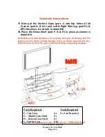
Page 14: ...R into place As shown in detail 12 18 Place the Glass Shelf part F G H in place as shown in detail 12 Note Make sure that the Glass sits correctly and goes all the way into the grooves on the Spine an...

Page 15: ...33 10944 Page 15 Option 2 CONSOLE for DLP s CRT s 19 Position assembled TV Stand against the wall in the part of the room you want to place your TV then with the help of a friend place the TV on the T...

Page 16: ...er area of the studs and level with each other Use the Mounting Frame part J as a template to mark the location of the second hole in each stud and drill another set of holes 2 1 2 deep with the 3 16...

Page 17: ...ly flush with the concrete surface even if there is a layer of drywall of other material in front 27 Now attach the Mounting Frame part J to the Wall using six Lag Bolts part 10 through the Lag Bolt W...

Page 18: ...nt Hardware bag for this Unit When properly installed this restraint can provide protection against the unexpected tipping of the unit due to small tremors bumps or climbing We strongly recommend moun...

Page 19: ...Please call for replacement parts or assistance 1 866 942 5362 VAS Furniture Mfg Inc Factory No 33 10944 Page 19 Your assembly should now be complete Thank you for your purchase...

Reviews: