background image

Varian, Inc. 

Frederick C. Campbell

Operations Manager

We
Wir
Nous
Nosotros
Wij
Noi

Lexington, MA, 02421-3133 USA 

121 Hartwell Avenue

Lexington, Massachusetts, USA

Varian, Inc. 

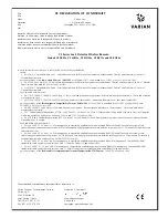
CE DECLARATION OF CONFORMITY

The authorized representative located within Community is:

Varian Vacuum Technologies (Torino)
Varian S.p.A
Via F.lli Varian.54
Leini (Torino) - Italy
Tel: (39) 011 997 9 111
Fax: (39) 011 997 9 350

declare under our sole responsibility that the product,
erklären, in alleniniger Verantwortung, daß dieses Produkt,
déclarons sous notre seule responsabilité que le produit,
declaramos, bajo nuestra sola responsabilidad, que el producto,
verklaren onder onze verantwoordelijkheid, dat het product,
dichiariamo sotto nostra unica responsabilità, che il prodotto,

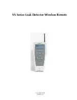
VS Series Leak Detector Wireless Remote

Models VS PR02x, VS MR15x, VS MD30x, VS BR15x and VS BD30x

to which this declaration relates is in conformity with the following standards:

Safety:

• EN 61010-1, Second Edition, 2001 - 

Safety Requirements for Electrical Equipment for Measurement, Control, and Laboratory Use-Part 1: 

General Requirements

per the provisions of the 

Low Voltage Directive 73/23/EEC 

of 19 February 1973 as Amended by 93/68/EEC, Article 13, of 22 July 1993.

• CAN/CSA-C22.2 No. 61010-1-04 - 

Safety Requirements for Electrical Equipment for Measurement, Control, and Laboratory Use-Part 1: General 

Requirements

 (Adopted IEC 61010-1:2001, MOD) 

• UL 61010-1, Second Edition, 2004 - 

Safety Requirements for Electrical Equipment for Measurement, Control, and Laboratory Use-Part 1: 

General Requirements

EMC Emission and Immunity:

• EN 55011:1998/A1: 1999/A2: 2002 Group 1 Class A: 

ISM radio-frequency equipment - Radio disturbance characteristics - Limits and methods 

of measurement (EU)

• EN 61326:1997/A1: 

1998 /A2:2001 Electrical equipment for measurement, control and laboratory use - EMC requirements (EU) 

per the provisions of the 

Electromagnetic Compatibility Directive 89/336/EEC

 of 3 May 1989 as Amended by 92/31/EEC of 28 April 1992 and 

93/68/EEC, Article 5 of 22 July 1993

• AS/NZS CISPR 11:2004 Class A: 

ISM radio-frequency equipment - Electromagnetic disturbance characteristics - Limits and methods of 

measurement (Australia)

• FCC: Code of Federal Regulations, 47CFR: 2004, Part 15C, Section 15.24, 

Class A: Telecommunication, Radio Frequency Devices, Operation 

within the bands 902-928 MHz, 2400-2483.5 MHz, and 5725-5850 MHz

 (USA)

• CAN/IC: Radio Standard Specification RSS-210, Issue 5, 

for Low Power License- Exempt Radio communication Devices of Industry Canada

November 2001 (Canada)

EMC and Radio Spectrum Matters:

• EN 300 328-1 V1.3.1 (2001-12) 

Electromagnetic compatibility and Radio spectrum Matters (ERM): Wiband Transmission systems; Data 

transmitting equipment operating in the 2.4 GHz ISM band and using spread spectrum modulation techniques; Part 1: Technical characteristics and 
test conditions (EU)

• EN 300 328-2 V1.2.1 (2001-12) 

Electromagnetic compatibility and Radio spectrum Matters (ERM): Wiband Transmission systems; Data 

transmitting equipment operating in the 2.4 GHz ISM band and using spread spectrum modulation techniques; Part 2: Harmonized EN covering 
essential requirements under article 3.2 of R&TTE Directive (EU)

• EN 301 489-1 V1.3.1 (2001-09) 

Electromagnetic compatibility and Radio spectrum Matters (ERM): Electromagnetic Compatibility (EMC) 

standard for radio equipment and services: Part 1: Common Technical requirements (EU)

• EN 301 489-17 V1.1.1 (2001-09) 

Electromagnetic compatibility and Radio spectrum Matters (ERM): Electromagnetic Compatibility (EMC) 

standard for radio equipment and services: Part 17: Specific conditions for Wideband data and HIPERLAN equipment (EU)

per the provisions of the 

 Radio and Telecommunications Terminal Equipment (R&TTE) Directive

, 1999/5/EC of 9 March 1999

Summary of Contents for VS BD30x

Page 1: ...D R A F T 1 1 2 0 6 OPERATION MANUAL vacuum technologies VS Series Leak Detector Wireless Remote Manual No 699909945 Revision A October 2006 ...

Page 2: ...D R A F T 1 1 2 0 6 Copyright 2006 Varian Inc VS Series Leak Detector Wireless Remote ...

Page 3: ...n including representatives of Seller which are inconsistent or in conflict with the terms of this warranty shall not be binding upon Seller unless reduced to writing and approved by an officer of Seller Warranty Replacement and Adjustment All claims under warranty must be made promptly after occurrence of circumstances giving rise thereto and must be received within the applicable warranty period...

Page 4: ...VS Series Leak Detector Wireless Remote This page intentionally left blank D R A F T 1 1 2 0 6 ...

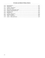
Page 5: ...2 1 1 2 Front Panel Display and Controls 1 3 Section 2 Operating the Wireless Remote 2 1 2 1 Startup and Shutdown 2 1 2 1 1 Startup 2 1 2 1 2 Shutdown 2 1 2 2 Screens 2 2 2 2 1 Basic Functions 2 2 2 2 2 Home Screen 2 4 2 2 3 Speaker Volume Setup Screen 2 7 2 2 4 Backlight Screen 2 8 2 2 5 Communication Setup Screen 2 10 2 2 5 1 Choose Leak Detector 2 11 2 2 5 2 Scan and Choose a Leak Detector 2 14...

Page 6: ...VS Series Leak Detector Wireless Remote This page intentionally left blank D R A F T 1 1 2 0 6 ...

Page 7: ...2 11 2 11 Speaker Volume Setup Screen 2 11 2 12 Backlight Screen 2 12 2 13 Setup Screen 2 12 2 14 Select Screen 2 12 2 15 Choose LD Screen 2 13 2 16 Link Screen 2 13 2 17 No Available LD 2 13 2 18 Speaker Volume Setup Screen 2 14 2 19 Backlight Screen 2 14 2 20 Setup Screen 2 14 2 21 Select Screen 2 15 2 22 Search Screen 2 15 2 23 Searching Screen 2 15 2 24 Choose LD Screen 2 16 2 25 Link Screen 2...

Page 8: ...Contrast Initial Screen 2 22 2 42 Sleep Timer Screen 2 22 2 43 Sleep Timer Configuration Screen 2 23 2 44 Speaker Volume Setup Screen 2 24 2 45 Backlight Screen 2 24 2 46 Setup Screen 2 24 2 47 Contrast Initial Screen 2 25 2 48 Sleep Timer Screen 2 25 2 49 Version Initial Screen 2 25 2 50 Version Information Screen 2 26 ...

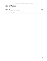
Page 9: ...VS Series Leak Detector Wireless Remote D R A F T 1 1 2 0 6 ix List of Tables Table Title Page 2 1 Screen Basic Functional Items 2 2 2 2 Status Messages 2 3 A 1 Wireless Remote Specifications A 1 ...

Page 10: ...VS Series Leak Detector Wireless Remote This page intentionally left blank D R A F T 1 1 2 0 6 ...

Page 11: ...equipment for measurement control and laboratory use EMC requirements EU per the provisions of the Electromagnetic Compatibility Directive 89 336 EEC of 3 May 1989 as Amended by 92 31 EEC of 28 April 1992 and 93 68 EEC Article 5 of 22 July 1993 AS NZS CISPR 11 2004 Class A ISM radio frequency equipment Electromagnetic disturbance characteristics Limits and methods of measurement Australia FCC Code...

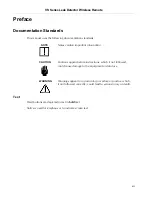
Page 12: ...ortant information CAUTION Cautions appear before instructions which if not followed could cause damage to the equipment or data loss WARNING Warnings appear for a particular procedure or practice which if not followed correctly could lead to serious injury or death Text Hard buttons are depicted in text in bold text Italics is used for emphasis or to indicate screen text ...

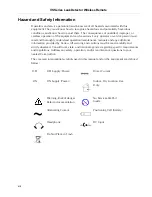
Page 13: ...ize hazardous and potentially hazardous conditions and know how to avoid them The consequences of unskilled improper or careless operation of the equipment can be serious Every operator or service person must read and thoroughly understand operation maintenance manuals and any additional information provided by Varian All warning and cautions must be read carefully and strictly observed Consult lo...

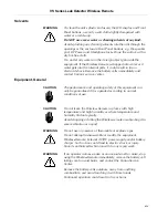
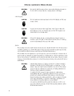
Page 14: ...ance and operating safety of this equipment can only be guaranteed if it is operated according to normal conditions of use CAUTION Do not leave the Wireless Remote in places with high temperature and high humidity or where temperature and humidity fluctuate greatly Avoid dropping or hitting the Wireless remote or subjecting it to severe vibration or impact WARNING Do not use in presence of flammab...

Page 15: ...t to point or point to multipoint client server or peer to peer architecture One RF transceiver is configured as a server and there can be one or many clients To establish synchronization between transceivers the server emits a beacon Upon detecting a beacon a client transceiver informs its host and a RF link is established WARNING The Wireless Remote complies with Part 15 of the FCC Rules Operati...

Page 16: ...hcraft P N760 or equivalent Barrel s polarization Internal External Input Voltage 100 to 240 VAC 50 60 Hz Power connection Wall mount plug in type AC plug country dependable Desktop with an IEC60320 C14 AC inlet and detachable power cord Detachable power cord for North America Rated 10 A 125 V Cordage 300 V PVC Wire 3 x 18 AWG Plug NEMA 5 15P Connector IEC 60320 C13 Length 6 min UL CSA approved Wo...

Page 17: ...t depends on the cell type and the operating schedule of the unit see Table 1 The wireless device is capable of operating continuously for eight hours with the backlight OFF when batteries are fresh WARNING Take the follow actions to maximize battery safety when using Primary alkaline Ultra Ultra Industrial or Nickel Oxy or Lithium Iron e2 Lithium and or Rechargeable NiMH cells Never use the cells...

Page 18: ...emperature range between 59 F and 77 F If the area too warm the cells will not be fully charged If the area is too cold the cells can permanently loose their ability to charge For best performance let the fresh fast charged NiMH cells cool to room temperature before using it in the unit If not used immediately remove the NiMH cells from the charger and then apply a topping charge before use Do not...

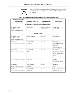
Page 19: ...A NH15 12 14 h cycle 500 cycles NiMH cell 1 2 V 2200 mAh Primary Cells Eveready battery co Energizer www energizer com AA e2 Lithium L91 12 15 Lithium Iron 1 5V 3000 mAh Duracell www duracell com oem AA Alkaline NX1500 6 10 Nickel Oxy Hydroxide Power Pix NiOx 1 5V 1500mAh Panasonic www panasonic com AA Alkaline ZR6 6 10 Nickel Oxy Hydroxide Xtreme Power or Oxiride 1 5V Duracell www duracell com oe...

Page 20: ...ISM band These limits are designed to provide reasonable protection against harmful interference when it is operated in a commercial environment This equipment generates uses and can radiate RF energy which if not installed and used in accordance with the instructional manual can cause harmful interference to radio communications When this equipment is operated in a commercial environment operatio...

Page 21: ...ollution Degree 2 environment for a Hand Held Electrical Equipment for Measurement Control and Laboratory Use Any modifications on the unit made by the user are liable to cause non compliance with regulations or affect the EMC performance and the safety of the product Varian cannot be held responsible for consequences resulting from such intervention The unit can be damaged by Radio Frequency RF a...

Page 22: ...site support Please see our catalog or contact us to learn about available services Contacting Varian See the back cover of this manual for a listing of our sales and service offices Internet users Send email to Customer Service and Technical Support at vtl customer service varianinc com Visit our web site at www varianinc com vacuum Order on line at www evarian com ...

Page 23: ...internal calibrated leak Zero the VS unit s leak rate and helium background Able to operate on 19 different channels which are selectable at the leak detector See the VS Series Helium Mass Spectrometer Leak Detector Operations Manual for details The wireless device can operate multiple systems remote handsets and leak detectors in a common area with only one link active at any moment A leak detect...

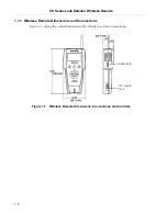
Page 24: ...ote 1 2 D R A F T 1 1 2 0 6 1 1 1 Wireless Remote Dimensions and Connections Figure 1 1 shows the units dimensions with callouts to system connections Figure 1 1 Wireless Remote Dimensions Connections and Controls Audio Jack DC Input Jack ...

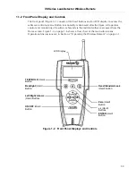
Page 25: ... control and monitoring of results is achieved via the resident software accessed from the Home screen Figure 1 3 on page 1 6 shows a flow chart of the main sub screens Operational discussions are in Section 2 Operating the Wireless Remote on page 2 1 Figure 1 2 Front Panel Displays and Controls LCD Display TEST HOLD Hard Button ON OFF Hard Button Backlight Hard Button Zero Hard Button Read Standa...

Page 26: ...ameters are represented on the screen in alphanumeric format a bold font in this manual Leak Rate Bar Graph The large bar graph displays the leak rate in one of two forms A linear bar graph Mantissa 2 divisions per segment 10 segments per decade A logarithmic bar graph Mantissa 2 divisions per segment The displayable ranges for each of the UNITS that the system can operate in are For LOG display b...

Page 27: ...croll through the screen features ON OFF ON A momentary press turns the wireless remote ON OFF Pressing and holding the OFF button turns the wireless remote OFF Hold the button down until the display goes blank approximately three seconds Read Standard Leak Toggles the standard leak ON OFF for system access ZERO Zeroes out the helium signal indicated on the display These buttons increment decremen...

Page 28: ...rough a series of screens which are navigated as in Figure 1 3 Figure 1 3 Screen Flow BACKLIGHT CONTRAST SETUP SLEEP TIMER VERSION INFO BATTERY LEVEL SETUP AUDIO ON OFF COMMUNICATIONS SPEAKER VOLUME SETUP SET UP MAC ADDRESS CHOOSE LD SIGNAL POWER HOME SETUP SETUP CHOOSE SCAN AND CHOOSE ...

Page 29: ...remote was Connected in a session to a leak detector at the previous power down and it can connect to the same leak detector again then the remote s display transitions to the HOME screen Not connected at the previous power down or it can no longer establish a session with the same leak detector the remote goes into Searching mode Searching mode is also accessed manually via the Setup screen NOTE ...

Page 30: ...emote keypad TEST HOLD READ STANDARD LEAK and Zero buttons The wireless remote updates the LCD display for leak rate and status approximately once per second 2 2 1 Basic Functions Table 2 1 Screen Basic Functional Items Item Function Appears on screens more than one level from the Home screen Highlight this button and press the Enter button to return directly to the Home screen Saves all values on...

Page 31: ... NO CONNECTION Indicates the connection has failed This may be momentary or it may indicate that the wireless remote s signal is obstructed wireless remote s is out of range leak detector is not configured for wire less communication leak detector is off VS Series Leak Detector Wireless Remote D R A F T 1 1 2 0 6 2 3 Table 2 2 explains the status messages that appear on the wireless remote Home sc...

Page 32: ...s the ENTER button to select that function To set the volume on off 1 Press the or to select the speaker icon on the Home screen 2 Press the ENTER button once to set the speaker off 3 Press the ENTER button again to return the speaker to on The volume level is restored to the level it was at prior to being turned off The Home screen displays a summary of the following status configuration settings...

Page 33: ... units setting for the leak detector it displays the appropriate ranges for LOG mode When the helium leak rate signal is either Under or Over range a single arrow or blinks within the leak rate bar graph to indicate that condition Figure 2 2 Home Screen Under and Over Indicators 5 Battery Power Level Icon The battery power level indicator appears only on the Home screen and represents the voltage ...

Page 34: ...24 7 Speaker Icon The speaker icon appears only on the Home screen and accesses the audio ON OFF function 8 RF Signal Strength Icon The RF signal strength icon appears only on the Home screen and represents the strength of RF analogue signal If the wireless remote is too far from the host leak detector the RF signal will be weak or undetectable vertical bars 9 Leak Detector Status The current leak...

Page 35: ...high as it passes through each decade The audio response corresponds directly to the size of the leak To set the volume 1 Press the or hard buttons to highlight the Home screen Tools icon and press Enter and the Speaker Volume setup screen appears Figure 2 4 Figure 2 4 Speaker Volume Setup Screen 2 Press Enter and the configuration screen appears Figure 2 5 Figure 2 5 Speaker Volume Setup Configur...

Page 36: ...r the LCD backlight intensity To set the backlight intensity level 1 Press the or hard buttons to highlight the Home screen Tools icon and press Enter and the Speaker Volume setup screen appears Figure 2 4 Figure 2 6 Speaker Volume Setup Screen 2 Press the once and the Backlight screen appears Figure 2 7 Figure 2 7 Backlight Screen ...

Page 37: ... configuration screen appears Figure 2 8 Figure 2 8 Backlight Setup Configuration Screen 4 Press the buttons to set desired backlight intensity level e g 80 5 Press Enter and Figure 2 7 reappears 6 Press the to highlight the Home screen icon and press Enter and the Home screen reappears ...

Page 38: ... Use this screen to navigate to the three sub screens to Use the SELECT screen to choose a leak detector from a list of leak detectors within communications range that are is not already connected While up to 10 leak detectors MAC addresses can be configured at one time only one connection can be active Section 2 2 5 1 Choose Leak Detector on page 2 11 Use the Search screen to scan the area for av...

Page 39: ... is set to the same channel selecting the leak detector via MAC address Once the desired MAC channel is shown in the Choose LD screen pressing ENTER causes the wireless remote to attempt to establish a session with that leak detector The leak detector and wireless remote MAC addresses are viewed in the MAC Address screen see Section 2 2 5 3 MAC Address Verification on page 2 16 Figure 2 10 Choose ...

Page 40: ... 1 2 0 6 2 Press the and the Backlight screen appears Figure 2 12 Figure 2 12 Backlight Screen 3 Press the and the Setup screen appears Figure 2 13 Figure 2 13 Setup Screen 4 Press Enter and the the Select screen appears Figure 2 14 Figure 2 14 Select Screen ...

Page 41: ...ailable leak detectors e g 23 3C 0C 7 Press Enter and the Link screen appears Figure 2 16 for one to three seconds and then the Home screen reappears Figure 2 16 Link Screen NOTE If the Choose LD process finds a leak detector that is currently in session with another remote the leak detector won t allow a new session and Figure 2 17 appears Press the ENTER button to establish the new session Figur...

Page 42: ...from the Home screen 1 Press the or hard buttons to highlight the Home screen Tools icon and press Enter and the Speaker Volume screen appears Figure 2 18 Figure 2 18 Speaker Volume Setup Screen 2 Press the and the Backlight screen appears Figure 2 19 Figure 2 19 Backlight Screen 3 Press the and the Setup screen appears Figure 2 20 Figure 2 20 Setup Screen ...

Page 43: ...d the the Select screen appears Figure 2 21 Figure 2 21 Select Screen 5 Press the and the Search screen appears Figure 2 22 Figure 2 22 Search Screen 6 Press Enter and the Searching screen appears Figure 2 23 followed by the Choose LD screen Figure 2 24 Figure 2 23 Searching Screen ...

Page 44: ...en 2 2 5 3 MAC Address Verification Use this screen to see the MAC addresses of both the leak detector and the wireless remote that is communicating with the leak detector If the MAC address of the previous leak detector is unknown the display leaves the leak detector MAC address blank To view and verify the MAC addresses from the Home screen 1 Press the or hard buttons to highlight the Home scree...

Page 45: ...0 6 2 17 2 Press the and the Backlight screen appears Figure 2 27 Figure 2 27 Backlight Screen 3 Press the and the Setup screen appears Figure 2 28 Figure 2 28 Setup Screen 4 Press Enter and the the Select screen appears Figure 2 29 Figure 2 29 Select Screen ...

Page 46: ...ress the and the Mac Addresses screen appears Figure 2 31 Figure 2 31 MAC Addresses Screen 7 Press Enter and the Mac Addresses screen appears Figure 2 32 Figure 2 32 Verify MAC Addresses Screen 8 Press Enter and the Mac Addresses screen reappears Figure 2 31 9 Press the to highlight the Home screen icon and press Enter and the Home screen reappears ...

Page 47: ...t To set the contrast level 1 Press the or hard buttons to highlight the Home screen Tools icon and press Enter and the Speaker Volume screen appears Figure 2 33 Figure 2 33 Speaker Volume Setup Screen 2 Press the and the Backlight screen appears Figure 2 34 Figure 2 34 Backlight Screen 3 Press the and the Setup screen appears Figure 2 35 Figure 2 35 Setup Screen ...

Page 48: ...rast Initial Screen 5 Press Enter and the configuration screen appears Figure 2 37 Figure 2 37 Contrast Configuration 6 Press the or hard buttons to set the desired contrast level e g 51 7 Press Enter and the Contrast screen reappears Figure 2 36 8 Press the to highlight the Home screen icon and press Enter and the Home screen reappears ...

Page 49: ...mount of time the unit automatically shuts down to save battery life The range is from 1 to 60 minutes When set to OFF the sleep timer never automatically shuts the wireless remote down To set the sleep timer 1 Press the or hard buttons to highlight the Home screen Tools icon and press Enter and the Speaker Volume screen appears Figure 2 38 Figure 2 38 Speaker Volume Setup Screen 2 Press the and t...

Page 50: ...0 6 3 Press the and the Setup screen appears Figure 2 40 Figure 2 40 Setup Screen 4 Press the and the Contrast screen appears Figure 2 41 Figure 2 41 Contrast Initial Screen 5 Press the and the Sleep Timer screen appears Figure 2 42 Figure 2 42 Sleep Timer Screen ...

Page 51: ...s Figure 2 43 Figure 2 43 Sleep Timer Configuration Screen 7 Press the or hard buttons to set the desired sleep time from 1 to 60 minutes or OFF infinite time ON 8 Press Enter and the Sleep Timer screen reappears Figure 2 42 9 Press the to highlight the Home screen icon and press Enter and the Home screen reappears ...

Page 52: ...ss Remote To see the Version Info 1 Press the or hard buttons to highlight the Home screen Tools icon and press Enter and the Speaker Volume screen appears Figure 2 44 Figure 2 44 Speaker Volume Setup Screen 2 Press the and the Backlight screen appears Figure 2 45 Figure 2 45 Backlight Screen 3 Press the and the Setup screen appears Figure 2 46 Figure 2 46 Setup Screen ...

Page 53: ...Press the and the Contrast screen appears Figure 2 47 Figure 2 47 Contrast Initial Screen 5 Press the and the Sleep Timer screen appears Figure 2 48 Figure 2 48 Sleep Timer Screen 6 Press the and the Version screen appears Figure 2 49 Figure 2 49 Version Initial Screen ...

Page 54: ...1 2 0 6 7 Press Enter and the information screen appears Figure 2 50 Figure 2 50 Version Information Screen 8 Press Enter and the Version screen reappears Figure 2 49 9 Press the to highlight the Home screen icon and press Enter and the Home screen reappears ...

Page 55: ... EIRP with 3 dBi gain antenna Operational Range Up to 100 m 328 indoors based on 2 dBi gain antenna Antenna 1 2 Wave Dipole Gain 2 dBi Centurion P N WCP2400 MMCX2 Handheld Unit Nearson P N S181FL 4 RMM 2450S LD Base Station Power Requirements Average power 1 0 W Battery Supply 4 four AA size cells Type Primary e2 alkaline or Lithium Iron or Rechargeable NiMH cells suitable for the high current pul...

Page 56: ...al Speaker Impedance 8 0 Ohm Frequency Response 200 6000 Hz Sound Level 85 dB min 1 0 Ft Headphones Mono 3 5 mm male plug Impedance 32 0 Ohm Frequency Response 100 10000 Hz Note stereo headphones can be used with a 3 5 mm mono male to stereo female adapter the adapter will not produce stereo sound Installation Indoor use only Altitude up to 2000 m 6 400 Material Group III POLLUTION DEGREE 2 accord...

Page 57: ......

Page 58: ... gu Seoul Korea 135 280 Tel 82 2 3452 2452 Fax 82 2 3452 2451 Mexico Varian S A Concepcion Beistegui No 109 Col Del Valle C P 03100 Mexico D F Tel 52 5 523 9465 Fax 52 5 523 9472 Russia Central coordination through Varian Inc via F lli Varian 54 10040 Leini Torino Italy Tel 39 011 997 9 252 Fax 39 011 997 9 316 Taiwan Varian Technologies Asia Ltd 18F 13 No 79 Hsin Tai Wu Road Sec 1 Hsi Chih Taipei...

Reviews: