Vari F-530.1 Instructions For Use Manual Download Page 10


F-530.1


10 

b)  Rear:  -  Handlebar  grips  or  Flat  cross-beam  between  the  frame  tubes  when  the 

handlebars are folded. 

 
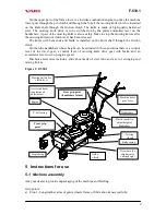
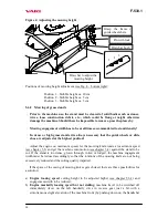
If you assemble the machine yourself, follow the below instructions: 
1.  Dismount guide wheels from knife casing (2x nut M10, 2x spanner No. 17 or 16); 
2.  Dismount clamps from handlebars and frame (2x nut + bolt M8, 2x spanner No. 13); 
3.  Turn  handlebars  and  fit  them  on  frame  tubes.  To  fix  the  handlebars,  use  bolts 

M8x50  and  plastic  rosebits  with  flat washers. Bowden cables are to be attached to 
handlebars by means of two tightening tapes; 

4.  Push  the  draw  bars  for  cutting  height  adjustment,  which  are  on  guide  wheels,  into 

bushes on the knife casing and fix the guide wheels into feet on the knife casing (2x 
nut M10 with flat washer, 2x spanner No. 17 or 16). Secure the draw bars by means 
of two lock pins. 


Figure 2: Machine assembly 


5.2  Putting into operation 




The machine is delivered without operational fillings of the engine! 




Read  the  instruction  for  engine  use  thoroughly!  You  can  prevent  a  possible 
damage to the engine. 

 
1.  Fill the engine with the prescribed types and volumes of oil and petrol. 
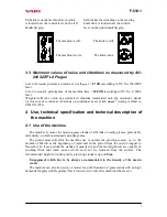
2.  Move  the  accelerator  lever  into  the  front  position  (

CHOKE

).  By  pulling  on  the 

manual starter start the engine (see guidelines for engine use). 

3.  Let the new or cold engine running for about 30 seconds on the choke (accelerator 

lever  in  the 

CHOKE

  position);  then  move  the  accelerator  lever  into  the  position 

MAX

 and let the engine running in this position for about 30 seconds. 




Don’t leave the machine alone when doing this. 


Bowden  cables  to  be  fastened  to 
handlebars by tightening tapes 


Summary of Contents for F-530.1

Page 1: ...Mulcher F 530 1 Instructions for use 2003...

Page 2: ...d mixing knife complement 16 6 Maintenance care and storage 16 6 1 Lubrication 16 6 1 1 Gear oil replacement and refilling 16 6 1 2 Engine oil replacement 18 6 1 3 Table of machine lubrication 18 6 2...

Page 3: ...original record Type F 530 1 Engine type Briggs Stratton INTEK EDGE 60 OHV Briggs Stratton INTEK PRO 65 Machine serial number Engine serial number Date of delivery sale Supplier Address Telephone Fax...

Page 4: ...aining and provide instructions on machine control for operators and to keep records on these trainings and briefings Should some instructions in the manual be intelligible you are encouraged to conta...

Page 5: ...damage the machine If these cannot be removed don t work the places The machine is equipped with the rotating working knife Maximum circumferential speed is 109 m sec 1 Therefore see to it that other...

Page 6: ...et into the mowing knife working space is prohibited danger of injury 4 Keep a safe distance from the machine in operation danger of injury by flying material fragments and objects Self sticker locate...

Page 7: ...testing method to CSN EN 1033 4 Use technical specification and technical description of the machine 4 1 Use of the machine The mulcher is meant for mowing grass stands of all kinds of stalky grasses...

Page 8: ...OHV Cylinder volume cm3 189 Drilling x lift mm 68 3 x 51 8 Max Mk RPM N m RPM 10 9 2500 Max engine speed RPM 3600 Tank capacity litres 1 5 Petrol leadless oct no 91 95 Oil filling litres 0 77 Oil SAE...

Page 9: ...whose height can be adjusted in three positions there is a control lever of the travel gear a control lever of mowing knife drive gear with brake and an accelerator lever to set up engine speed Machin...

Page 10: ...knife casing 2x nut M10 with flat washer 2x spanner No 17 or 16 Secure the draw bars by means of two lock pins Figure 2 Machine assembly 5 2 Putting into operation The machine is delivered without op...

Page 11: ...rotating and the engine does not stall The start of the mowing knife is accompanied with a partial slippage of the V belt and associated phenomena such as whistling rattling etc The phenomenon usuall...

Page 12: ...ar clutch Bowden cable of mowing knife brake Bowden cable of tightening pulley of mowing knife drive V belt Right hand rail Left handrail STOP position of accelerator lever engine does not run MIN tur...

Page 13: ...ny delay The levers will return to their zero position the machine and the mowing knife will come to a stop while the engine is still running at adjusted rotations this is why it is to be switched off...

Page 14: ...mowing knife rotate at maximum speed see chapter 5 3 and get the machine into motion see chapter 5 4 against the stand to be cut If the stand is too dense grown through rotten or lodged the machine en...

Page 15: ...d be wearing protective gloves or you can also use a fitted piece of branch etc 5 6 3 Arrestment of guide wheel suspensions In order to better guide the machine while driving along the countour line o...

Page 16: ...e of the machine will prevent its early wear ensuring at the same time a correct functioning of all its parts Follow all instructions for intervals of machine maintenance and adjustment It is advices...

Page 17: ...ments are MOGUL TRANS 90 or MOGUL TRANS 80W 90 Oil replacement should be made when the box is warm oil can be drained easily 1 Clean around the oil plugs Underlay the machine and secure it so that a s...

Page 18: ...lt casing min 2x yes 8 1 All cables on the input to Bowdens on the output from adjustment bolts min 2x min 2x yes yes Both swivel seatings of rotary lever in the gearbox after belt casing disassembly...

Page 19: ...ing barrel spanner No 16 b Take the knife out plane the blade and sharpen cutting edges Inclination of the sharpened blade should be 25 with respect to the lower plane of the knife The knife has to be...

Page 20: ...iction lamella Friction pin steel Belleville washer Knife shaft Cover packing piece Friction pad ferodo Upper knife mixing Complete knife 52 cm Pin 6x8 mm modification Friction pad ferodo Friction lam...

Page 21: ...rect and full functioning of the gear d Put the engine back in place Pins on the belt pulley must fall into holes in the driven part of the coupling mounted on the gearbox Bolt the engine with three s...

Page 22: ...s in the pulley Bowden and in the Bowden of machine travel gear clutch must be without slackness slightly tense Safety nuts in all adjustment bolts should be tightened by using two spanners No 10 or N...

Page 23: ...1 see Fig 12 Brake cam lever insufficiently lubricated To be oiled Brake performance is insufficient Worn lining Contact service shop Wheel travel gear clutch does not switch off Incorrectly adjusted...

Page 24: ...about 200 hours 6 9 Washing and cleaning of the machine At cleaning and washing the machine proceed to observe valid regulations and laws on the protection of water courses and other water resources...

Page 25: ...by hand in the direction of forward travel The free wheel must be clicking Figure 13 Free wheel on the left wheel 6 10Storage 1 Prior to a longer storage clean the machine from all impurities debris...

Page 26: ...ear of manufacture 2 Ordering number given by manufacturer and its name in the component list 3 Number of ordered pieces separately for each item 4 Precise address telephone number fax number or e mai...

Page 27: ...F 530 1 27 9 1 Knife casing and guide wheels...

Page 28: ...xible split pin 160 606 PRILLINGER 182 511 2 20 Wheel 200x20x50 ETOP 182 512 2 21 Circular plug 085 034 25x3 SUNAP Neratovice 182 513 2 22 Circular plug 085 068 22x1 1 5 SUNAP Neratovice 189 524 2 23...

Page 29: ...F 530 1 29 9 2 Mowing knife drive...

Page 30: ...x pr 36 x 0 1 32 0 9220 024 110 012 3 15 Shim block pr 30 5 x pr 20 2 x 0 3 32 0 9220 058 127 041 3 16 Pulley ADELA 632 0 3325 040 189 586 1 17 Spring of brake shoes 632 0 9746 044 189 511 1 18 Spring...

Page 31: ...F 530 1 31 9 3 Handlebars...

Page 32: ...42 182 530 1 7 Buffer spring N 77 16 42 85 GUMOKOV 182 531 2 8 Rubber grip ART 733 ern PLASTISCHE CASSANO 195 518 2 9 Gas lever AE 653 H l 850mm START 182 532 1 10 Straight way plastic rosebit M8 pr 5...

Page 33: ...F 530 1 33 9 4 Wheel drive gear...

Page 34: ...19 Inner tube 3 50 8 182 521 2 20 Rim 3 00 8 ETOP 182 522 2 21 Ball pr 7 144 189 575 8 22 Chain 08B1 25 l nk SN 02 3311 182 523 1 23 Connecting link 08B1 SN 02 3311 182 524 1 24 Bolt M8x20 SN 02 1103...

Page 35: ...F 530 1 35 9 5 Gearbox...

Page 36: ...89 528 1 13 Bearing 6005 SN 02 4630 994 9302 2 14 Bearing 6202 SN 02 4630 994 3131 1 15 Bearing 6203 SN 02 4630 994 3159 1 16 Shaft packing 25x47x7 SN 02 9401 0 124 505 2 17 Shaft packing 17x30x7 SN 0...

Page 37: ...F 530 1 37 9 6 Swinging and mixing knives slide shoe...

Page 38: ...0 9311 135 182 018 1 4 Service package Tajfun 45 12 9 3182 010 168 025 1 Slide shoe Pos Name Size Drawing Standard Order No Pcs 1 Slide shoe 22 9 1646 022 182 050 1 2 Complete draw bar 22 9 1364 012 1...

Page 39: ...of product in question and specified parameters for the whole period of warranty The manufacturer does not answer for defects of the product resulting from current wear or from the product s use for p...

Page 40: ...placed parts new warranty of months Parts Repair made by Stamp and signature 2nd Warranty service Machine type Serial No Date Serviced by Stamp and signature 3rd Warranty service Date of complaint Dat...

Page 41: ...F 530 1 41 Text and illustrations c 2002 VARI a s Publication No VL 061 2002...

Reviews: