6
3
5
4
1
2
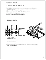
Clamping Handle
PLAN VIEW
FORMING ROLLS
As viewed from bottom
Moveable
Fixed Side
F
ro
n
t
Side
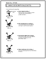
FIG. 1
FIG. 2
FIG. 3
4
1
5
2
6
3
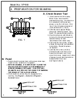
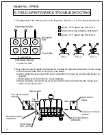
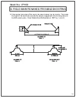
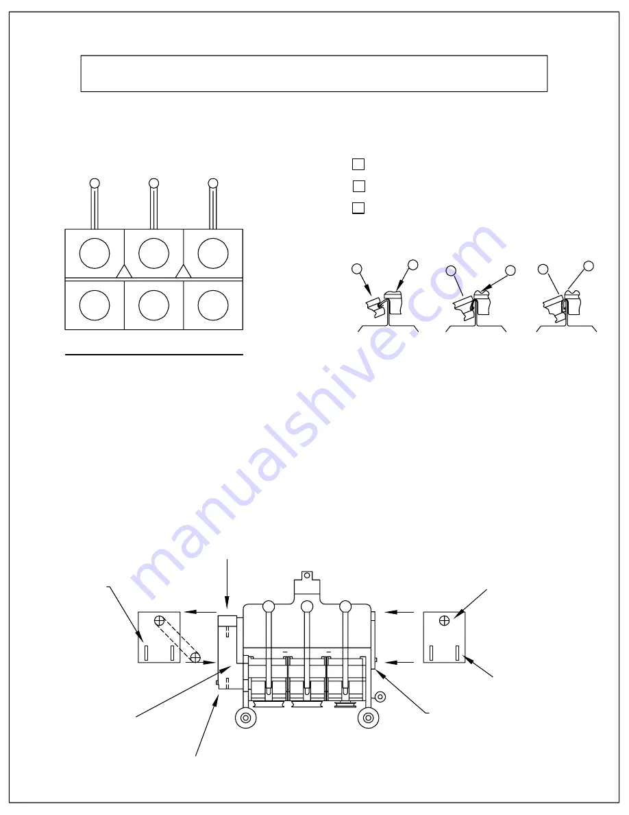
7. The alignment of the forming rolls is very important. (See fig. 1, 2 & 3 for proper placement)
Approx. 0.75" gap at top. Roll #1 & 4
Fiber roll touches at bottom. Roll #2 & 5
Approx. 0.11" gap at top. Roll #3 & 6.
1
3
2
8. Drive chain at rear of seamer tool should be checked for tightness (after each 8 hours of use).
a. Remove rear chain drive cover (one (1) set screw).
b. Motor mount brackets are at front & rear of electric motor (two (2) at each end) loosen as
required.
c. Reset tightness of drive chain to "snug" tightness.
d. Reset mounting screws (two (2) at each end) at front & rear motor mounts. Make sure
motor is level or set even.
Front Motor Mount
Adjustable
Motor Mount
Screw
Two (2) set screws
w/slots
Chain Guard
Chain Guard
One (1) Screw
Rear Motor Mount
Adjustable
Two (2) set screws
w/slots
Top
Bottom
Drive
Sprocket
Model No. VP-900
12
6. FIELD MAINTENANCE/TROUBLESHOOTING
Summary of Contents for SSR 900
Page 2: ......
Page 20: ...Model No VPHC 17 17 1 VP SSR HAND CRIMPING TOOL...

