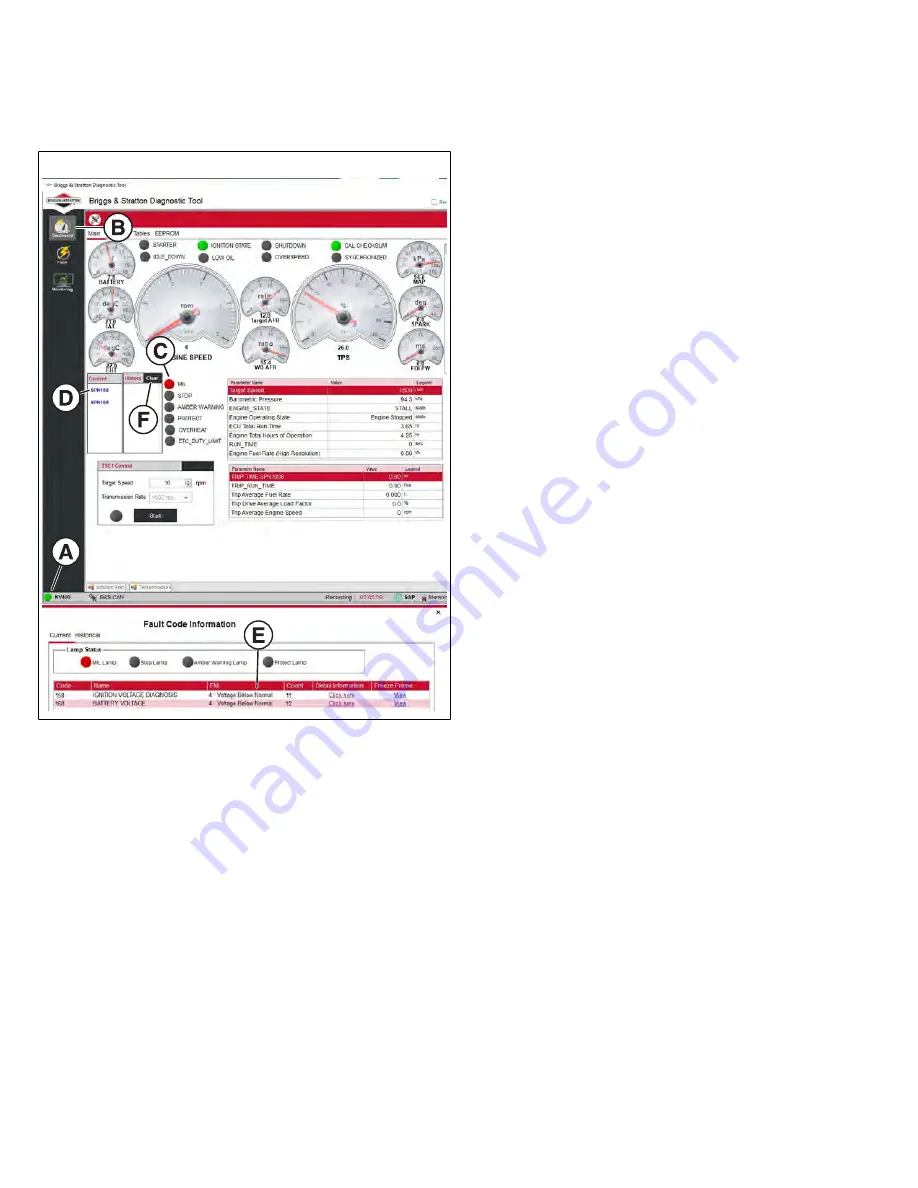
6. Turn Ignition ON, Engine OFF.
The Diagnostic Tool can take up to 30 seconds to
connect to the engine. Once established, the connection
indicator light (
A
, Figure 4) becomes solid green and
displays the name of the connected device.
4
7. Select the
Dashboard
icon (
B
) to view the Dashboard.
8. The
CHECK ENGINE
light (
C
) is red if a current fault
code is present.
9. Observe the
Current
codes display. Hover the cursor
over the blue hyperlink (
D
) to display a description of
the SPN fault code. Click on the hyperlink to read the
associated FMI (
E
).
10. Click
Clear
(
F
) to erase both current and historic DTCs.
11. Turn Ignition OFF.
12. Wait ten seconds, and then disconnect the Diagnostic
Tool cables and power supply.
NOTE:
While the Diagnostic Tool provides “live” data for
analysis, it is not a standalone diagnostic tool for resolving
DTCs, but must be used in conjunction with the Diagnostic
Tables in this manual for the most efficient and effective
diagnosis.
Back Probe Connector Terminals
Do not insert probes into terminals on the mating side of
any connector. The diameter of the test probes can damage
terminals.
1. Obtain a digital volt ohm meter (DVOM) and a back
probe wire set.
2. Carefully slide metal pin on probe between the rubber
seal and wire insulation on the back side (wire end) of
the connector.
3. Gently push the pin in until it stops. Stop pushing when
the pin “bottoms out,” or when the plastic sheath is very
close to the connector housing.
DO NOT
force the pin into the connector as terminal and/
or probe pin damage can occur. Probe travel may be
stopped by contact with insulation or core crimps. Try
again after removing and re-positioning probe pin.
IMPORTANT:
• Use care to avoid deforming connector terminals,
either by forcing the probe too far into the cavity or
by using a probe that is too large. If terminal damage
is suspected, test for proper terminal contact.
• A deformed terminal can cause a poor connection
resulting in intermittent problems or even complete
component failure. Do not use paper clips or
other substitute devices as they also can damage
terminals.
• Do not probe through connector seals, wire
insulation, secondary ignition wires, boots, etc.
Damage can occur that is not readily apparent and
tiny holes can result in water intrusion, which leads
to corrosion and eventual component failure.
Avoid ECM Damage
A surge in voltage, current or both, is called a voltage spike.
Voltage spikes can cause major damage to the ECM.
To avoid ECM failure due to accidentally induced voltage
spikes, always observe the following precautions:
•
Do not start engine if battery cable connections are
loose.
•
Do not use a battery charger to start engine.
•
Turn Ignition OFF before disconnecting and/or
connecting battery cables.
•
When disconnecting battery, always disconnect battery
negative (-) cable first.
•
When connecting battery, always connect battery
positive (+) cable first.
•
When charging battery, turn Ignition OFF and remove
battery negative cable (black) from battery negative (-)
terminal.
•
If electric welding on vehicle, remove battery negative
cable (black) from battery negative (-) terminal, and
disconnect the ECM electrical connector(s).
14
Not for
Reproduction
Summary of Contents for 25E300
Page 1: ...Vanguard EFI Diagnostics and Repair 25E300 REPAIR MANUAL N o t f o r R e p r o d u c t i o n...
Page 18: ...Model 25E300 EFI Component Locations 19 N o t f o r R e p r o d u c t i o n...
Page 26: ...Speed vs Voltage Table 8 27 N o t f o r R e p r o d u c t i o n...
Page 61: ...25E300 Wiring Harness Diagram 62 vanguardpower com N o t f o r R e p r o d u c t i o n...
Page 62: ...63 N o t f o r R e p r o d u c t i o n...
Page 88: ...Model 25E300 Fuel Hose Location and Routing Tankless 89 N o t f o r R e p r o d u c t i o n...


