background image

SECTION 5: MAINTENANCE

AIR N ARC

®


I

-

300 SERIES ALL-IN-ONE POWER SYSTEM

®

PAGE - 50

090045-OP_r1

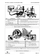
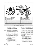
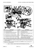
KEY

DESCRIPTION

KEY

DESCRIPTION

A

UPPER IDLER SHEAVE BOLT

G

2

DRIVE BELT: SMOOTH SIDE = OUTSIDE

B

UPPER IDLER SHEAVE

H

WELDER DRIVE PULLEY

C

TENSIONER PLATE (FOR UPPER IDLER)

J

AC GENERATOR PULLEY

D

TENSIONER PLATE ANCHOR SCREW

K

IDLER (LOWER - FOR COMPRESSOR UNIT 
SHEAVE)

E

ANCHOR HOLE FOR TORQUE WRENCH

L

COMPRESSOR DRIVE BELT 

I


F

TENSIONER PLATE ADJUSTMENT/SET BOLT

M

CLUTCH SHEAVE (FRONT: COMPRESSOR 
DRIVE) & STUB SHAFT SHEAVE (REAR: GEN-
ERATOR/HYDRAULIC PUMP DRIVE)

G

GENERATOR/HYDRAULIC PUMP DRIVE BELT 

G

1

DRIVE BELT: TRACTION SIDE = INSIDE

N

HYDRAULIC PUMP DRIVE SHEAVE

Compressor drive belt must be removed before maintenance can be performed on the generator/hydraulic pump drive 

belt. Refer to 

Section 5.4.3.2

 for instructions on removing the compressor drive belt, for purpose of gaining generator 

/ hydraulic belt access.

Order Generator / Hydraulic Pump Serpentine Belt Replacement no. 

DR272436. 

For Compressor Serpentine Belt 

replacement, refer to 

Section 5.4.3.2

.

Figure 5-7: Generator / Hydraulic Pump Serpentine Belt Replacement Positioning

M

K

G

1

N

G

2

G

1

G

2

G

2

G

1

G

H

G

J

M

N

H

BELT LAYOUT

J

B

M

K

N

L

N

G

1

K

G

2

M

A

B

C

D

E

F

B

Summary of Contents for AIR N ARC I 300 SERIES

Page 1: ...nuine Vanair Parts Inspect and replace damaged components before operation Substituting non Vanguard Oil or non genuine Vanair filter components WILL VOID THE COMPRESSOR WARRANTY Vanair Manufacturing Inc 10896 West 300 North Michigan City IN 46360 Phone 219 879 5100 800 526 8817 Service Fax 219 879 5335 Parts Fax 219 879 5340 Sales Fax 219 879 5800 www vanair com KEEP THE MANUAL WITH THE VEHICLE N...

Page 2: ...ts for three 3 years NOTE Engines are warranted separately by the engine manufacturer Consumable products such as filters and electrodes are not covered This warranty does not cover damage caused by accident misuse or negligence Any disassembly of major components must be approved by Vanair to avoid voiding of warranty The Warranty Service Department must be notified prior to any and all work bein...

Page 3: ... SPACES CAN CAUSE A BUILD UP OF NOXIOUS FUMES AND OVERHEATING 3 1 4 5 ARC RAYS CAN BURN EYES AND SKIN 3 1 4 6 WELDING CAN CAUSE FIRE AND EXPLOSION 4 1 4 7 FLYING METAL CAN INJURE EYES 4 1 4 8 HOT PARTS CAN CAUSE SEVERE BURNS 4 1 4 9 NOISE CAN DAMAGE HEARING 4 1 4 10 MAGNETIC FIELDS CAN AFFECT PACEMAKERS 4 1 4 11 CYLINDERS CAN EXPLODE IF DAMAGED 5 1 5 ENGINE HAZARDS 5 1 5 1 BATTERY EXPLOSION CAN BL...

Page 4: ...ONS 7 1 7 3 HOSE AND TUBING INSPECTION 8 1 7 4 HOSE AND TUBING REPLACEMENT 8 1 7 5 HOT PARTS CAN CAUSE SEVERE BURNS 8 1 7 6 HYDRAULIC CYLINDERS MAY HOLD A FUNCTION IN POSITION EVEN WHEN THE PUMP IS OFF 8 1 7 7 HYDRAULIC PIPING REPLACEMENT MUST CONFORM TO SAEJ1065 SPECIFICATIONS 8 1 7 8 DO NOT HEAT HYDRAULIC PIPE 8 1 7 9 RELIEVE HYDRAULIC SYSTEM PRESSURE BEFORE REMOVING ANY COMPONENTS FROM THE SYST...

Page 5: ...2 MACHINE CANOPY ACCESS SAFETY SWITCHES 13 1 13 DISPOSING OF MACHINE FLUIDS 13 SECTION 2 SPECIFICATIONS 15 TABLE 2A ENGINE HYDRAULIC SYSTEM WELDER AND GENERATOR SPECIFICATIONS 15 TABLE 2B SPECIFICATIONS AIR COMPRESSOR 16 TABLE 2C SPECIFICATIONS UNIT WEIGHT AND DIMENSIONS 16 TABLE 2D GENUINE VANGUARD OIL CHARACTERISTICS 16 SECTION 3 INSTALLATION 17 3 1 AIR N ARC I 300 SERIES ALL IN ONE MACHINE PACK...

Page 6: ...1 CONNECTION DISCONNECTION SEQUENCE AND OPERATION 33 4 8 USING THE START OVERRIDE SWITH TO JUMP START THE VEHICLE 33 4 9 OPERATING THE HYDRAULIC PUMP 34 4 10 EXTREME CONDITION OPERATION 34 4 10 1 COLD WEATHER OPERATION 34 4 10 2 HIGH TEMPERATURE OPERATION 35 4 10 3 HIGH DUST CONTENT OPERATION 36 4 10 4 HIGH ALTITUDE OPERATION 36 SECTION 5 MAINTENANCE 37 5 1 GENERAL INFORMATION 37 5 2 ROUTINE MAINT...

Page 7: ...IDE 56 SECTION 7 ILLUSTRATED PARTS LIST 65 7 1 PARTS ORDERING PROCEDURE 65 TABLE 7A RECOMMENDED SPARE PARTS LIST 66 7 2 AIR N ARC I 300 SYSTEMS ASSEMBLIES 68 7 3 AIR STORAGE ASSEMBLY 70 7 4 COMPRESSOR AND PARTS ASSEMBLY 1 OF 2 72 7 4 COMPRESSOR AND PARTS ASSEMBLY 2 OF 2 74 7 5 COOLING SYSTEM 76 7 6 FRAME AND CANOPY ASSEMBLY 1 OF 2 78 7 6 FRAME AND CANOPY ASSEMBLY 2 OF 2 80 7 7 INSTRUMENT PANEL 82 ...

Page 8: ...AND PLATE LOCATIONS 2 OF 4 107 7 14 DECAL AND PLATE LOCATIONS 3 OF 4 108 7 14 DECAL AND PLATE LOCATIONS 4 OF 4 109 7 15 WIRING DIAGRAM AIR N ARC I 300 SERIES 110 7 16 WIRING DIAGRAM SWITCHES AND LIGHTS 111 7 17 SCHEMATIC DIAGRAM HYDRO CRANE O C NO TOOL 112 7 18 SCHEMATIC DIAGRAM HYDRO CRANE C C NO TOOL 113 7 19 SCHEMATIC DIAGRAM COMPRESSOR FLOW 114 7 20 HOSE INSTALLATION GUIDE 115 ...

Page 9: ...and also the number of operational hours available Note that the above information will also need to be included on the Return Material Authorization Form per Step 6 this form is necessary for warranty processing if the warranty claim is deemed valid by the service case review 3 Contact the Vanair Service Department by phone 1 219 879 5100 to speak with a Service Technician 4 Vanair Service will t...

Page 10: ...locations of plate mounting D WELDER GENERATOR SERIAL TAG E AC GENERATOR SERIAL PLATE SERIAL LOCATION Figure W 1 Machine Serial Number Locations E D C A PN CODE KVA COSPHI D C V A BEARINGS GE269530 SN 5XXX PHASE 1 SERVICE S1 INS CL H 6 8 V 120 240 A 55 7 28 3 1 Hz 60 RPM 3600 CONNECTION II I Kg 23 7 IP 21 J 0098 6203 2ZC3 DATE 2011 10 OVERLOAD FOR 2 h I N A 24 h PERIOD 800 526 8817 www vanair com ...

Page 11: ... collect Freight costs will be addressed at the time the claim is closed The customer pays any additional costs for warranty parts delivered through expedited services i e Next Day Second Day VANAIR WILL NEVER ACCEPT ANY INVOICES FOR PARTS RETURNED ANY PARTS RETURNED VIA INVOICE WILL BE RETURNED FREIGHT COLLECT NO PARTS ARE TO BE RETURNED FREIGHT COLLECT Vanair Mfg Inc strives to continuously impr...

Page 12: ...PAGE X 090045 OP_r1 BLANK PAGE ...

Page 13: ...ing an operation Specific definitions of theses bordered instructions are as follows IMPORTANT It is mandatory that all operators read this manual before operating or servicing the Air N Arc I 300 Series All In One Power System Failure to do so could result in death bodily injury or damage to equipment DANGER Identifies actions or conditions which will cause death severe injury equipment damage or...

Page 14: ... is confined or if there is a danger of falling Additional safety precautions are required when working in electrically hazardous conditions such as in damp locations or while wearing wet clothing on metal structures such as floors gratings or scaffolds when in cramped positions such as sitting kneeling or lying or when there is a high risk of unavoidable or accidental contact with the work piece ...

Page 15: ...level causing injury or death Be sure the breathing air is safe DO NOT weld in locations near degreasing cleaning or spraying operations The heat and rays of the arc can react with vapors to form highly toxic and irritating gases DO NOT weld on coated metals such as galvanized lead or cadmium plated steel unless the coating is removed from the weld area the area is well ventilated and while wearin...

Page 16: ...g to AWSF4 1 See Section 1 10 Principal Safety Standards Connect ground cable as close to the welding area as practical to prevent welding current from traveling long possibly unknown paths and causing electric shock sparks and fire hazards DO NOT use welder to thaw frozen pipes Remove stick electrode from holder or cut off welding wire at contact tip when not in use Wear oil free protective garme...

Page 17: ...r valve Keep protective cap in place over valve except when cylinder is in use or connected for use Use the right equipment correct procedures and sufficient number of persons to lift and move cylinders Read and follow instructions on compressed gas cylinders associated equipment and Compressed Gas Association CGA publication P 1 listed in Safety Standards 1 5 ENGINE HAZARDS 1 5 1 BATTERY EXPLOSIO...

Page 18: ...so that it will not turn while working on generator components 1 5 4 HOT PARTS CAN CAUSE SEVERE BURNS DO NOT touch hot parts bare handed Allow cooling period before working on equipment 1 5 5 ENGINE EXHAUST GASSES CAN KILL If used in a closed area vent engine exhaust outside and away from any building air intakes Check the fuel system at a well ventilated open space 1 5 6 ENCLOSED SPACES CAN CAUSE...

Page 19: ...icing Use only genuine Air N Arc replacement parts 1 7 HYDRAULIC PUMP HAZARDS 1 7 1 CONTENTS UNDER PRESSURE DO NOT operate the hydraulic system if a leak is present Serious injury may result Hydraulic systems operate under very high pressure Hydraulic fluid escaping from a pressurized system can penetrate unprotected body tissue DO NOT inspect for hydraulic leaks with bare hands or other exposed b...

Page 20: ... the hydraulic system thoroughly clean any spilled oil from the equipment DO NOT spill any hydraulic fluids on the ground Clean any hydraulic fluids from your skin as soon as you have completed maintenance and repairs Dispose of used oil and system filters as required by law 1 7 6 HYDRAULIC CYLINDERS MAY HOLD A FUNCTION IN POSITION EVEN WHEN THE PUMP IS OFF Hydraulic cylinders can be holding a fun...

Page 21: ...n incorrect test gauge could result in serious injury if the gauge fails Use properly rated hydraulic hoses to allow the test gauge to be read away from moving parts and functions 1 7 12 SYSTEM MODIFICATION PROHIBITED A Vanair pump or pump control must not be modified in any way without authorization from Vanair Modifications may not comply with safety standards including ANSI safety standards and...

Page 22: ...TION OPERATION AND MAINTENANCE 1 8 1 FALLING UNIT CAN CAUSE INJURY Use lifting bail to lift unit and properly installed accessories only Lift and support unit only with proper equipment and correct procedures If using lift forks to move unit be sure forks are long enough to extend beyond opposite side of unit 1 8 2 OVERHEATING CAN DAMAGE MOTORS Turn off or unplug equipment before starting or stopp...

Page 23: ...SE INTERFERENCE Electromagnetic energy can interfere with sensitive electronic equipment such as microprocessors computers and computer driven equipment such as robots Ensure all equipment in the welding area is electromagnetically compatible To reduce possible interference keep weld cables as short as possible close together and down low such as on the floor Locate welding operation 100 meters fr...

Page 24: ...her Hot Work NFPA Standard 51B from National Fire Protection Association P O Box 9101 1 Battery March Park Quincy MA 02269 9101 phone 617 770 3000 web site www nfpa org OSHA Occupational Safety and Health Standards for General Industry Title 29 Code of Federal Regulations CFR Part 1910 Subpart Q and Part 1926 Subpart J from U S Government Printing Office Superintendent of Documents P O Box 371954 ...

Page 25: ... the switch is bypassed and the hood may be raised without detriment to the operating state of the machine 1 13 DISPOSING OF MACHINE FLUIDS Always dispose of machine fluids under the guidance of all applicable local regional and or federal law Vanair encourages recycling when allowed For additional information consult the container label of the fluid in question CAUTION The machine is not designed...

Page 26: ...IATOR J COMPRESSOR UNIT Z COMPRESSOR AIR OIL COALESCER SEPARATOR K LOAD SENSE PRESSURE GAUGE SERVICE AA RADIATOR FILL CAP L COMPRESSOR OIL DRAIN TUBE END CAP BB ENGINE AIR FILTER M ENGINE OIL DRAIN END CAP CC ENGINE N RELAYS not all relays are shown DD LIFTING BAIL P PRESSURE SWITCH EE BATTERY Q COMPRESSOR FLUID FILL PORT FF FUSES not all fuses are shown NOTE The above figure does not show all maj...

Page 27: ... PSI Hyd 5 5 Hyd Flow w Cmpr Low and High Speed 2000 PSI Hyd 2 1 Rated Welder Output 300A High Frequency DC CC DC CV 100 Duty Cycle 270 Amps Welding Leads 25 or 50 Ft Optional Welder CC Max Volts 60 min Welder CC Max Amps 285 min Welder CC VDC Max Amp 15 Welder CV Min Volts 15 Welder CV Max Volts 40 DC 12 Volt Charge Volts Idle 14 DC 12 Volt Boost Volts 16 I For specification and requirements rega...

Page 28: ...ng below 0 F 18 C Electrical System 12 VDC Cooling System Air to Oil Heat Exchanger Instrument Gauges Pressure and Hour Meter Adjustable Air Pressure Control Settings Cut in Pressure 100 PSI 5 Cut out Pressure 40 CFM 135 PSI 15 Air Service Outlets Two 2 on Control Panel One 1 on Machine tank TABLE 2C SPECIFICATIONS UNIT WEIGHT AND DIMENSIONSI Dimensions Length Width Height WeightII wet WeightII dr...

Page 29: ...ce Fax 219 879 5335 www vanair com to report missing items incorrect part numbers or other discrepancies DISCLAIMER DO NOT install in any enclosed space without first contacting Vanair WARNING The lifting bail on the I 300 package is rated to the machine weight only DO NOT overtax the lifting bail WARNING Grounding must consist of a minimum two 2 gauge wire between the instrument panel the machine...

Page 30: ...ake into account the additional cooling and maintenance space requirements before locating the machine mounting position 3 3 MOUNTING THE MACHINE Refer to Figure 3 1 Once all of the factors listed in Section 3 2 have been considered and the machine placement location has been resolved the machine must be fully unpacked from its crate mounting 3 3 1 MACHINE STABILIZATION Machine should be mounted t...

Page 31: ...AIR N ARC I 300 SERIES ALL IN ONE POWER SYSTEM SECTION 3 INSTALLATION 090045 OP_r1 PAGE 19 Figure 3 1 Installation and Dimensions Diagram Part 1 of 2 050790 001_r1_1of3 ...

Page 32: ...SECTION 3 INSTALLATION AIR N ARC I 300 SERIES ALL IN ONE POWER SYSTEM PAGE 20 090045 OP_r1 Figure 3 2 Installation and Dimensions Diagram Part 2 of 2 050790 001_r0_2of3 050790 001_r0_2of3 ...

Page 33: ...AIR N ARC I 300 SERIES ALL IN ONE POWER SYSTEM SECTION 3 INSTALLATION 090045 OP_r1 PAGE 21 Figure 3 3 Installation and Dimensions Diagram Optional Hydraulic Tank Assembly PA6120139ID_r2 ...

Page 34: ...M Refer to Figure 3 2 for hydraulic pump system connections Please take into consideration the following The hydraulic flow and pressure requirements of the system The duty cycle and ambient operating temperatures Other hydraulic equipment which may share that same hydraulic supply system Vanair recommends a dedicated pump and hydraulic circuit The hydraulic hoses must be run into the package to t...

Page 35: ...ded PTFE tube with stainless steel single wire braid The working pressure and temperature ratings should be 200 psi air 300 F similar to PA87939 3 8 FUEL LINE SIPHON Refer to Figure 3 5 for fuel line air bleed nut location on the engine and the following instructions 1 Open the bleed nut to siphon off any air in the line Turn on the pump allow air to escape and tighten the nut after all air is out...

Page 36: ...SECTION 3 INSTALLATION AIR N ARC I 300 SERIES ALL IN ONE POWER SYSTEM PAGE 24 090045 OP_r1 Figure 3 5 Fuel Line Bleed Nut receiving air in fuel line ...

Page 37: ...nt valve which will vent all pressure to the atmosphere Refer to Figure 4 1 Open the compressor fill cap SLOWLY contents under pressure to make sure all pressure has been relieved CAUTION Compressors and engines generate heat and create hot surfaces Use caution when operating and servicing equipment Some surfaces and components may be hot IMPORTANT Do not operate machine without hydraulic connecti...

Page 38: ... confirm that the master power switch located in the vehicle cab is in the ON position 2 On the machine panel ensure that the Welder Generator Hydraulic Pump and Compressor switches are in their OFF positions 3 Turn the machine s key switch to ON position 4 Turn crane remote ON 5 Select the ENGINE START switch and hold until engine starts If engine does not crank and has fault tripped on LOW OIL P...

Page 39: ...NDICATOR LAMP G START OVERRIDE SWITCH T ALTERNATOR FAIL INDICATOR LAMP H TACH HOUR METER U HIGH TEMPERATURE INDICATOR LAMP J GENERATOR THROTTLE CONTROL ON OFF SWITCH V LOW OIL PRESSURE INDICATOR LAMP K HYDRAULIC ON OFF SWITCH W PREHEAT START CONDITION GLOW PLUG INDICA TOR LAMP L COMPRESSOR ON OFF SWITCH Figure 4 2 Instrument Panel TACH HOUR 1 10 SHOCK HAZARD CIRCUITS ARE LIVE WHEN MACHINE IS AT FU...

Page 40: ...nto the generator panel 4 Turn the Welder Generator Hydraulic Pump and Compressor switches on the control panel to their OFF positions 5 Allow machine to run at idle for 3 5 minutes to allow for a cool down sequence 6 Turn the Crane Remote switch or master power switch or Engine Control Switch to the OFF position 4 3 ENGINE THROTTLE CONTROL FUNCTIONS The engine speed is controlled by two factors 1...

Page 41: ...he electrode clamp 4 Start the engine See Section 4 2 Machine Start up and Shutdown Procedure 5 On the control panel place the CC CV switch in CC mode Place the DC Charger Welder switch in welder mode 6 Adjust the power dial to the appropriate amperage setting for the material and the electrode being used See Table 4A ELECTRODE SPECIFICATIONS for electrode amperage ratings At anytime during weldin...

Page 42: ...etal Arc Welding GMAW NOTE If a longer welding lead is desired optional 25 and 50 ft lead segments may be purchased from Vanair Manufacturing Inc for a maximum lead length of 100 ft TABLE 4A ELECTRODE SPECIFICATIONS METAL THICKNESS ELECTRODE SIZE WELDING AMPERES 1 16 1 8 3 32 50 90 1 8 1 4 1 8 90 140 1 4 3 8 5 32 120 180 3 8 1 2 3 16 150 230 TABLE 4B WELDING ROD TYPE POLARITY AND FLUX CODES DIGIT ...

Page 43: ... specifications for general information on the power requirements of common power tools motors and extension cords in order to confirm power draw limitations If the thermal overload circuit breakers on the generator are tripped due to an overload condition press the white reset buttons on the generator panel to reset the breakers Figure 4 5 NOTE When using a spool gun an adapter with contactor mus...

Page 44: ...n the air tools being used The operator is responsible for regulating the air pressure when necessary See Section 5 4 2 Adjusting the Pressure Setting NOTE The pressurized air system requires routine maintenance See Table 5A Maintenance Schedule in Section 5 to learn about important maintenance procedures NOTE The moisture drain valve on the air tank may be accessed at any time including while the...

Page 45: ...le switch to the OFF position 7 Allow engine to idle down then shut down the engine 8 Now it is safe to disconnect the clamps from the battery being charged and the battery cable connection on the front of the machine 4 8 USING THE START OVERRIDE SWITCH TO JUMP START THE VEHICLE If the vehicle battery voltage is too low to start the vehicle the override switch will allow for the vehicle to be star...

Page 46: ...d to a serious problem If the ambient temperature varies largely the environment is dusty or the engine is operated at a high altitude the engine performance is directly or indirectly influenced Machine review and maintenance check schedules should be more frequent than the normal suggestions given in Section 5 Table 5A Maintenance Schedule Become familiar with the alternative operation approaches...

Page 47: ...ult the Engine Operator s Manual 4 10 2 HIGH TEMPERATURE OPERATION High compartment temperatures can be caused by high ambient temperatures small engine room soundproof cases and other reasons Among these the most important factor is the temperature of the intake and cooling air Reduce load duty cycle to less than 60 when operating in ambient temperatures above 104 F 40 C Extra care should be take...

Page 48: ... prevent foreign matter from entering it is necessary to ensure the security of the air intake system to prevent the component parts from being damaged This can be accomplished by performing more frequent monitoring of the air filters air evacutator valve on compressor air filter and radiator coolers and their immediate surroundings when operating in areas that contain a high dust content If the p...

Page 49: ...TELY Always clearly tag the start up instrumentation against accidental system start ups during maintenance WARNING DO NOT remove caps plugs and or other components when compressor is running or pressurized Stop compressor and de pressurize system prior to maintenance of system Relieve the entire system pressure by opening the air tank drain vent valve which will vent all pressure to the atmospher...

Page 50: ...7 1 Parts Ordering Procedure and Table 7A Recommended Spare Parts List NOTE Follow the prescribed periodic maintenance PM schedule as recommended Perform the required PM schedule at recommended intervals Failure to follow this prescribed periodic maintenance at the recommended intervals will impair the package safety performance characteristics shorten the package s life and will negatively affect...

Page 51: ...ours KEY TASK DESCRIPTION ACTION TO TAKE REFERENCE 1 Check the coolant recovery tank level Add clean fresh water if low Recovery tank is marked with a FULL and LOW level indicator proper level is between these lines Do not overfill recovery tank For complete coolant change also refer to the Engine Operator s Manual WARNING Do not remove the radiator cap while coolant is hot When cool to the touch ...

Page 52: ...ually note any leaks or evidence of leaks around the compressor unit and hose connections Tighten any loose connection point where needed Repair or replace any damaged part Continued on next page TABLE 5A MAINTENANCE SCHEDULE WARNING Before performing maintenance Shut down machine relieve all system pressure and lock out all power as per the Safety Section of this manual NOTE THAT THE SYSTEM CAN B...

Page 53: ...ter will ensure that the compressor is protected Replace if air filter membrane is worn contains tears or pinholes or if filter is damaged Continued on next page TABLE 5A MAINTENANCE SCHEDULE WARNING Before performing maintenance Shut down machine relieve all system pressure and lock out all power as per the Safety Section of this manual NOTE THAT THE SYSTEM CAN BE STARTED REMOTELY Always clearly ...

Page 54: ...es and connections Clean and tighten as necessary Replace any worn cables 18 Inspect unit mounting bolts Tighten any loose mounting bolts as necessary Continued on next page TABLE 5A MAINTENANCE SCHEDULE WARNING Before performing maintenance Shut down machine relieve all system pressure and lock out all power as per the Safety Section of this manual NOTE THAT THE SYSTEM CAN BE STARTED REMOTELY Alw...

Page 55: ...r compressor and generator drive belts Replace and re tension the drive belts Consult Section 5 4 3 for belt tightening and belt replacement procedures 26 Inspect the generators and the automatic belt tensioner Ensure that the automatic belt tensioner is free of rough noisy or worn bearings Consult Section 5 4 3 for belt tightening and belt replacement procedures TABLE 5A MAINTENANCE SCHEDULE WARN...

Page 56: ... 5 5 2 Long Term Storage WARNING Follow all applicable safety recommendations as outlined in Section 1 Safety of this manual WARNING Before performing maintenance Shut down machine relieve all system pressure and lock out all power as per the Safety Section of this manual If machine is hot allow package to cool before removing any panel NOTE THAT THE SYSTEM CAN BE STARTED REMOTELY Always clearly t...

Page 57: ...essure switch body with the cover retaining screw 4 Close the hood and cycle the compressor several times to ensure that the correct pressures are set 5 If additional adjustments are needed repeat steps 1 through 4 until the correct pressures are set 5 4 3 RE TENSIONING AND REPLACING THE SERPENTINE DRIVE BELTS The compressor and generator are driven by the engine using two belts The belts will gen...

Page 58: ...bout the loosened but anchored mounting bolt Apply torque of 40 ft lbs 4 Once a position is achieved that accounts for a satisfactory tension in the belt torque the four 4 tensioner plate bolts A to 12 ft lbs to secure the tensioner into position 5 4 3 2 REPLACING THE AIR COMPRESSOR SERPENTINE DRIVE BELT To replace the air compressor serpentine belt consult Figures 5 4 and 5 5 and the following pr...

Page 59: ...5 4 3 for compressor belt replacement For Generator Hydraulic Pump Belt replacement refer to Section 5 4 3 4 Figure 5 3 Compressor Serpentine Belt Re tensioning F G A B C D E KEY DESCRIPTION KEY DESCRIPTION A CLUTCH RETAINING CABLE ASSEMBLY F WASHER B ELECTRICAL HARNESS CABLE CONNECTION AT CLUTCH G HARNESS CABLE CLAMPI C CLUTCH H CLUTCH RETAINING CABLE D RETAINING CABLE BOLT J CABLE CONNECTION HOL...

Page 60: ...s wire intact G washer F lock washer E and retaining cable bolt D into proper anchoring hole in the frame base Tighten the bolt securely 5 4 3 3 RE TENSIONING THE GENERATOR HYDRAULIC PUMP SERPENTINE DRIVE BELT To re tension the generator hydraulic pump serpentine belt consult Figure 5 6 and the following procedure 1 With the machine off and the ignition key removed open and remove the front panel ...

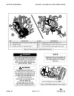
Page 61: ...order to access the generator hydraulic drive belt Refer to Section 5 4 3 2 for compressor serpentine belt removal Once the compressor drive belt is removed the worn generator serpentine belt can be replaced Refer to Figure 5 7 and the following steps 1 Using a 3 4 socket wrench loosen bolt F enough to allow pivoting of tensioner plate C to relieve enough tension on the upper idler sheave in order...

Page 62: ...HEAVE REAR GEN ERATOR HYDRAULIC PUMP DRIVE G GENERATOR HYDRAULIC PUMP DRIVE BELT G1 DRIVE BELT TRACTION SIDE INSIDE N HYDRAULIC PUMP DRIVE SHEAVE I Compressor drive belt must be removed before maintenance can be performed on the generator hydraulic pump drive belt Refer to Section 5 4 3 2 for instructions on removing the compressor drive belt for purpose of gaining generator hydraulic belt access ...

Page 63: ... to pivot along the grooves in the plate while still remaining in position 3 Use a 1 2 drive torque wrench applied to the square tensioning hole E to manually rotate the plate pump sheave about the loosened but anchored mounting bolt bottom bolt Apply torque of 51 in lbs as per Table 5B Measuring Belt Deflection for the proper tension measurement 4 Once a position is achieved that accounts for a s...

Page 64: ...to cool before removing any panel NOTE THAT THE SYSTEM CAN BE STARTED REMOTELY Always clearly tag the start up instrumentation against accidental system start ups during maintenance NOTE Replacement fuses can sometimes be found at local vendor carriers such as automobile supply stores hardware stores etc Order 15A Replacement Fuse no 265909 Figure 5 9 DC Welder Generator Fuse Location KEY DESCRIPT...

Page 65: ...ET B GENERATOR CIRCUIT BREAKERS 25A x 2 I C ENGINE OIL FILTER D DC GENERATOR E BATTERY BRACKET I Location orientation reference Replacement breaker covers boots also available KEY DESCRIPTION KEY DESCRIPTION A RELAYS x9 40 AMP E 15 AMP FUSE ENGINE START B ENGINE SHUTDOWN TIMER RELAY F 10 AMP FUSE COMPRESSOR C GROUND STUD G 10 AMP FUSE INSTRUMENT PANEL D 10 AMP FUSE THROTTLE Figure 5 11 Power Syste...

Page 66: ...stiffness or discoloration 5 5 2 LONG TERM STORAGE Disconnect the battery cable that is connected to the positive side of the battery Depressurize the air tank and open the drain valve on the tank Fill the fuel tank with fuel and fuel stabilizer to prevent moisture build up in the tank and start up to cycle fuel stabilizer throughout engine before storing After fuel stabilizer has been cycled cove...

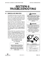
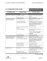
Page 67: ...efer to Table 5A Mainte nance Schedule for a typical maintenance regimen program Although Vanair strives to anticipate situations that may occur during the operation life of the machine package the Troubleshooting Guide may not cover all possible situations Be aware that additional trou bleshooting information may be found in other sources such as the Engine Operation Manual and the Generator Oper...

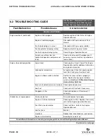
Page 68: ...ts start up of engine Close hood panel or check if roof switch is faulty See Section 1 12 Machine Canopy Access Safety Switches Low or dead battery voltage Recharge or replace battery Poor grounding Check and confirm ground connection Engine will not start Low fuel and or oil supply Check fuel gauge Check engine oil level Replenish as necessary Consult the Engine Operation Manual for additional in...

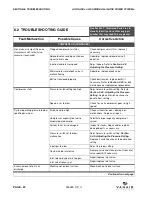
Page 69: ...ulty Replace pressure switch Defective Throttle Control Relay Solenoid not actuating Inspect replace if necessary Improper Control Operation Engine does not slow down Leak in control line Check for leaks replace line if necessary Pressure switch out of adjustment Adjust to proper pressure setting Refer to Section 5 4 2 Adjusting the Pressure Setting Replace if switch continues to deviate from sett...

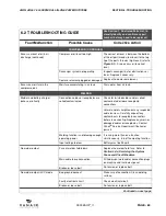
Page 70: ...t level Refer to Engine Overheats fault Engine shutdown switch activated Confirm that access door is properly in place Replace faulty engine shutdown switch see Section 1 12 Machine Canopy Access Safety Switches Excessive hydraulic pressure overload Check hydraulic pressure Low Fuel Check and refill fuel tank if necessary PLugged air filter Check and replace air filter element if necessary Gradual...

Page 71: ...Speed and the Engine Operation Manual Fan not operating Low oil check oil level and refill to proper level if necessary ensure machine is parked on a level surface Belt slip on hydraulic pump Refer to the hydraulic pump sub sections in Section 5 4 3 Re tensioning and Replacing the Serpentine Drive Belts Compressor shuts down with air demand present Compressor temperature switch opening Check compr...

Page 72: ...ompressor air filter Replace if necessary Pressure switch out of adjustment Reset pressure switch Refer to Section 5 4 2 Adjusting the Pressure Setting Replace if switch continues to deviate from setting Defective pressure switch Replace pressure switch Engine does not speed up Adjust speed control Consult Section 5 4 1 Adjusting the Engine Speed and the Engine Operation Manual Belt s slipping Re ...

Page 73: ...r damage wear kinks etc Re route re tie or replace if necessary refer to Section 7 20 Hose Installation Guide for assistance in running or checking hose lines Control line connections are not prop erly seated poor connection quality Check lines for proper seating ensure line ends have been cut cleanly and are square Refer to Section 7 20 Hose Installa tion Guide for assistance in running or checki...

Page 74: ...Check to see if compressor goes to high speed System operating pressure below specified minimum Air demand too high Check air tools for wear damage or malfunctions Replace or repair Compressor capacity too low to accommodate demand Substitute larger capacity compressor system System leaks or is damaged Inspect for leaks Repair and or replace damaged parts as necessary Pressure switch set too low m...

Page 75: ...cable tensions Carefully wipe off any contaminants to receptacle connectors before re connecting Replace any worn or damaged cables or receptacles Contact Vanair Service Department if behavior persists Welding function is not drawing enough operating power If running more than one function simultaneously turn off competing function Input voltage too low Battery must be 25 volts No welder output Fu...

Page 76: ...ion Manual Weak faulty or incorrect capacitor Check replace if necessary Serpentine belt damaged or not tensioned properly Re situate and adjust belt tension or replace belt if necessary Consult Section 5 4 3 Re tensioning and Replacing the Serpentine Belts High AC voltage Engine speed too high for demand Adjust speed control Consult Section 5 4 1 Adjusting the Engine Speed and the Engine Operatio...

Page 77: ...s manner contact the factory directly at the address or phone numbers below When ordering parts always indicate the Serial Number of the machine package This can be obtained from the Bill of Lading for the machine pack age or from the compressor unit serial number plate See Figure 7 1 for location of machine package serial plate Consult Table 7A Recommended Spare Parts List on the next page for a ...

Page 78: ...essor 1 14 DR272436 Belt Hydraulic Pump Drive and Generators 1 15 267306 Breaker Circuit 50A 1 16 CO270786 Breaker 25A 2 17 PR81817 Boot 25A Breaker 2 18 263173 Fuse 10 Amp 3 19 265909 Fuse 15 Amp 1 20 270501 Relay 40A 9 21 264325 Switch 240 F NC 1 22 HY270358 Motor Hydraulic Fan 1 23 CO62617 Breaker Circuit 20A 2 24 CO79106 Gauge Hour Meter 1 25 CO89649 Gauge Air Dry 1 26 PR270548 Boot Breaker 3 ...

Page 79: ... 5 5 2 Long Term Storage IMPORTANT The listing in the recommended spare parts list table contains items that require maintenance on a routine basis and also those parts that may require maintenance over the course of the compressor package s performance schedule Although this recommended list is pro offered as a comprehensive guide to replacement parts damage may occur to the machine beyond the sc...

Page 80: ...SECTION 7 ILLUSTRATED PARTS LIST AIR N ARC I 300 SERIES ALL IN ONE POWER SYSTEM PAGE 68 090045 OP_r1 7 2 AIR N ARC I 300 SYSTEMS ASSEMBLIES PA6130069 001ID_r0 ...

Page 81: ...62 001ID 1 7 6 5 INSTRUMENT PANEL PA6040047ID 1 7 7 6 ID GENERATORS AND PARTS PA6050012ID 1 7 8 7 ID HYDRAULIC PISTON PUMP ASSY PA6100036 001ID 1 7 9 II 8 ID ENGINE DRIVE PARTS PA6100056ID 1 7 10 9 ID ELECTRICAL SYSTEM I300D EM PA6120136ID 1 7 11 10 ID MANIFOLD ASSEMBLY PA6120134 03ID 1 7 12 11 ID HYDRAULIC TANK ASSEMBLY PA6120139ID 1 7 13 12 DECAL LOCATIONS 7 14 I For a detailed breakdown of the ...

Page 82: ...SECTION 7 ILLUSTRATED PARTS LIST AIR N ARC I 300 SERIES ALL IN ONE POWER SYSTEM PAGE 70 090045 OP_r1 7 3 AIR STORAGE ASSEMBLY PA6000079 001ID_r0 ...

Page 83: ...8769 004 1 6 GROMMET RUBBER 1 3 4X2 1 8X1 4 269302 1 7 PLUG PIPE 1 2 807800 020 1 8 NUT HEX FLANGE 5 16 18 825305 283 4 9 NUT HEX LOCKING 1 4 20 825504 145 2 10 ELBOW 45 DEG 1 2 MPT x 8 MJIC 860008 050 1 11 TANK AIR ACCUMULATOR 4 GAL A1269633 1 12 HOUSING CONNECTOR 350 AMP GRAY EL52049 1 13 SPACER NYLON 1 2 OD x 1 4 ID FA29036 2 14 PIPE BRASS BULKHEAD 1 8 NPT FI54337 1 15 VALVE BALL MINI 1 8NPT M ...

Page 84: ...SECTION 7 ILLUSTRATED PARTS LIST AIR N ARC I 300 SERIES ALL IN ONE POWER SYSTEM PAGE 72 090045 OP_r1 7 4 COMPRESSOR AND PARTS ASSEMBLY 1 OF 2 PA6010123ID_r2 1 of 2 ...

Page 85: ...ND II A1270372 1 12 OIL VANGUARD 3 5 QUARTS I 264626 0 88 gal 35 BRACKET COMPRESSOR MTG A1270373 2 13 ELBOW 1 2MPT X 1 2FJIC SWVL 90 268929 008 1 36 WASHER SHEAVE COMPRESSOR A1270884 1 14 COMPR PART VANAIR 31 EMC 12VDC STD SHAFT 269761 1 37 SHEAVE COMPRESSOR 8 GROOVE DR270371 1 15 TAG COMPR VANAIR 31 270610 1 38 BELT SERPENTINE GATORBACK 4080537 8 RIB X 53 75 LG EFFECTIVE LENGTH BLK RUBBER DR27584...

Page 86: ...SECTION 7 ILLUSTRATED PARTS LIST AIR N ARC I 300 SERIES ALL IN ONE POWER SYSTEM PAGE 74 090045 OP_r1 PA6010123ID_r2 2 of 2 7 4 COMPRESSOR AND PARTS ASSEMBLY 2 OF 2 ...

Page 87: ...ND II A1270372 1 12 OIL VANGUARD 3 5 QUARTS I 264626 0 88 gal 35 BRACKET COMPRESSOR MTG A1270373 2 13 ELBOW 1 2MPT X 1 2FJIC SWVL 90 268929 008 1 36 WASHER SHEAVE COMPRESSOR A1270884 1 14 COMPR PART VANAIR 31 EMC 12VDC STD SHAFT 269761 1 37 SHEAVE COMPRESSOR 8 GROOVE DR270371 1 15 TAG COMPR VANAIR 31 270610 1 38 BELT SERPENTINE GATORBACK 4080537 8 RIB X 53 75 LG EFFECTIVE LENGTH BLK RUBBER DR27584...

Page 88: ...SECTION 7 ILLUSTRATED PARTS LIST AIR N ARC I 300 SERIES ALL IN ONE POWER SYSTEM PAGE 76 090045 OP_r1 7 5 COOLING SYSTEM PA6020024ID_r10 ...

Page 89: ... 5 16 18 825205 273 4 23 SHROUD COOLER A1270375 1 8 NUT HEX FLANGE 5 16 18 825305 283 4 24 BRACKET COOLER LH A1270382 1 9 NUT HEX LOCKING 1 4 20 825504 145 4 25 BRACKET COOLER RH A1270383 1 10 CAPSCREW HEX GR5 1 4 20X 3 4 829104 075 4 26 HOSE RADIATOR 7 8 ID X 17 LG EN271127 1 11 CAPSCREW HEX GR5 5 16 18 x 1 829105 100 4 27 HOSE RAD 7 8 ID X 12 1 2 LG EN271127 1 12 CAPSCREW HEX GR5 5 16 18 x 4 829...

Page 90: ...SECTION 7 ILLUSTRATED PARTS LIST AIR N ARC I 300 SERIES ALL IN ONE POWER SYSTEM PAGE 78 090045 OP_r1 7 6 FRAME AND CANOPY ASSEMBLY 1 OF 2 PA6030062 001ID_r0 1 of 2 ...

Page 91: ...COMPR OIL FILTER FILL A1273055 1 12 SEAL RUBBER D TRIM LOK 1 X 1 X 17 15 16 LG 264138 1 37 CANOPY SIDE LH W ACCESS A1273056 1 13 SEAL KNOCKOUT 1 2 264443 1 38 PLATFORM I A1273058 1 14 LATCH SENTRY PANEL 267124 4 39 SWITCH PRESSURE ADJUSTABLE 50 175 PSI CO271659 1 15 CLIP TOOL ZINC 3 4 TO 1 1 8 272059 1 40 SWITCH HOOD SAFETY NO NC 15A 125V AC CO81774 2 16 45 DEG PTC SWIVEL MALE 272423 1 41 TANK 1 G...

Page 92: ...SECTION 7 ILLUSTRATED PARTS LIST AIR N ARC I 300 SERIES ALL IN ONE POWER SYSTEM PAGE 80 090045 OP_r1 7 6 FRAME AND CANOPY ASSEMBLY 2 OF 2 PA6030062ID 001_r0 2 of 2 ...

Page 93: ...COMPR OIL FILTER FILL A1273055 1 12 SEAL RUBBER D TRIM LOK 1 X 1 X 17 15 16 LG 264138 1 37 CANOPY SIDE LH W ACCESS A1273056 1 13 SEAL KNOCKOUT 1 2 264443 1 38 PLATFORM I A1273058 1 14 LATCH SENTRY PANEL 267124 4 39 SWITCH PRESSURE ADJUSTABLE 50 175 PSI CO271659 1 15 CLIP TOOL ZINC 3 4 TO 1 1 8 272059 1 40 SWITCH HOOD SAFETY NO NC 15A 125V AC CO81774 2 16 45 DEG PTC SWIVEL MALE 272423 1 41 TANK 1 G...

Page 94: ...SECTION 7 ILLUSTRATED PARTS LIST AIR N ARC I 300 SERIES ALL IN ONE POWER SYSTEM PAGE 82 090045 OP_r1 7 7 INSTRUMENT PANEL PA6040047ID_r2 ...

Page 95: ...W SER WASH 5 16 18 x 0 75 829705 075 2 44 HARNESS WELD CABLE JUMPER EP270171 1 15 WASHER FLAT 1 4 838204 071 2 45 HARNESS A C PNL TO MACHINE EP270230 1 16 WASHER LOCK 1 4 838504 062 6 46 HARNESS WIRE INST PNL DISPLAY EP270315 1 17 ELBOW 37FL 90M 08 x 1 2 860208 050 1 47 HARNESS WIRE INST PNL EP272404 1 18 PNL CNTRL BACK A1269489 1 48 SCREW PHILLIPS PAN HEAD 10 32 X 1 2 LG SS FA33542 7 19 CLAMP CNT...

Page 96: ...SECTION 7 ILLUSTRATED PARTS LIST AIR N ARC I 300 SERIES ALL IN ONE POWER SYSTEM PAGE 84 090045 OP_r1 7 8 GENERATORS AND PARTS PA6050012ID_r4 ...

Page 97: ... SCREW SER WASH 5 16 18 x 0 75 829705 075 1 11 SCREW SER WASH 5 16 18 x 1 829705 100 3 12 SCREW SER WASH 3 8 16 x 1 829706 100 2 13 WASHER FLAT 5 16 838205 071 8 14 WASHER FLAT 3 8 838206 071 2 15 WASHER FLAT 1 2 838208 112 5 16 WASHER LOCK 1 4 838504 062 3 17 WASHER LOCK 5 16 838505 078 4 18 WASHER LOCK 3 8 838506 094 2 19 WASHER LOCK 1 2 838508 125 1 20 BRACKET WELD GENERATOR A1269734 1 21 BRACK...

Page 98: ...SECTION 7 ILLUSTRATED PARTS LIST AIR N ARC I 300 SERIES ALL IN ONE POWER SYSTEM PAGE 86 090045 OP_r1 7 9 HYDRAULIC PUMP ASSEMBLY 1 OF 3 PA6100036ID 001_r1 1of3 ...

Page 99: ... P D DR269898 1 13 CAP FEMALE JIC 1 5 16 12 16 264322 006 1 39 BUSHING QD STYLE SDS 7 8 BORE X 1 4 KEYWAY DR271744 1 14 ADAPTER 16 FJIC X 8 MJIC 265008 020 1 40 IDLER 3 OD X 1 3 8 FLAT FACE DR272187 1 15 PLUG SAE O RING HOLLOW HEX 6 268081 005 1 41 ADAPTER 1 4 FNPT X 1 4 JIC FI273339 1 16 TEE RUN SWIVEL 3 8 JIC 268769 003 SS 1 42 PUMP HYD PISTON 0 86 DISP HY271640 1 17 TEE RUN SWIVEL 1 2 268769 00...

Page 100: ...SECTION 7 ILLUSTRATED PARTS LIST AIR N ARC I 300 SERIES ALL IN ONE POWER SYSTEM PAGE 88 090045 OP_r1 7 9 HYDRAULIC PUMP ASSEMBLY OPEN CENTER 2 OF 3 PA6100036ID 001_r1 2of3 ...

Page 101: ...16 18 UNF 2B 264322 002 1 11 CAP FEMALE JIC 3 4 16 8 264322 003 2 17 TEE RUN SWIVEL 1 2 268769 004 1 20 NUT HEX FLANGE 3 8 16 825306 347 2 36 PANEL COVER PLATFORM A1273259 1 37 DECAL LOAD SENSE DL273347 1 41 ADAPTER 1 4 FNPT X 1 4 JIC FI273339 1 43 GAUGE HYD PRESSURE PNL MTG HY273301 1 44 FILTER ELEMENT 3000PSI 25MIC HY273367 2 52 HOSE PRESSURE GAUGE LOAD SENSE TU273020 020 1 56 HOSE FILTER OUT TO...

Page 102: ...SECTION 7 ILLUSTRATED PARTS LIST AIR N ARC I 300 SERIES ALL IN ONE POWER SYSTEM PAGE 90 090045 OP_r1 7 9 HYDRAULIC PUMP ASSEMBLY CLOSED CENTER 3 OF 3 PA6100036ID 001_r1 3of3 ...

Page 103: ...6 JIC 9 16 18 UNF 2B 264322 002 1 11 CAP FEMALE JIC 3 4 16 8 264322 003 2 15 PLUG SAE O RING HOLLOW HEX 6 268081 005 1 17 TEE RUN SWIVEL 1 2 268769 004 1 20 NUT HEX FLANGE 3 8 16 825306 347 2 36 PANEL COVER PLATFORM A1273259 1 37 DECAL LOAD SENSE DL273347 1 41 ADAPTER 1 4 FNPT X 1 4 JIC FI273339 1 43 GAUGE HYD PRESSURE PNL MTG HY273301 1 55 HOSE FILTER OUT TO MANIFOLD TU273020 CC 1 PLEASE NOTE WHE...

Page 104: ...SECTION 7 ILLUSTRATED PARTS LIST AIR N ARC I 300 SERIES ALL IN ONE POWER SYSTEM PAGE 92 090045 OP_r1 7 10 ENGINE AND DRIVE PARTS 1 OF 2 PA6100056ID_r1 1 of 3 ...

Page 105: ...18 x 0 75 829705 075 2 12 CAPSCREW HEX 10MM 1 25 x 30MM GR10 9 269438 12 38 SCREW SER WASH 5 16 18 x 1 829705 100 2 13 FILTER AIR 6 90 DEG 269660 1 39 CAPSCREW HEX GR8 7 16 20UNF x 2 5 829807 250 1 14 GASKET MUFFLER REPLCMT KUBOTA D902 269961 1 40 SCREW MACH SHOULDER 1 2 x 3 LG 830508 300 2 15 HOSE FLEX 1 3 4 I D X 9 LG 270698 0 75 ft 41 SCREW ROUND HD 8 32 x 1 2 831601 050 2 16 NUT HEX 5 16 18 82...

Page 106: ...SECTION 7 ILLUSTRATED PARTS LIST AIR N ARC I 300 SERIES ALL IN ONE POWER SYSTEM PAGE 94 090045 OP_r1 7 10 ENGINE AND DRIVE PARTS 1 OF 2 CONTINUED PA6100056ID_r1 1 of 3 ...

Page 107: ...65 SUPPORT MACHINE LH A1270391 1 91 U BOLT 3 8 16 x 3 1 2 WD x 5 1 16 FA270399 2 66 BRACKET LIFTING BAR A1270392 1 92 WASHER 1 2ID x 1OD 2 PIECE FA37629 1 67 BRACKET AIR FILTER SUPPORT A1270394 1 93 SHIPPED WITH ENGINE FUEL FILTER 1 68 BRACKET FUEL FILTER A1270395 1 94 TIES THERMAL STAINLESS STEEL HA42205 5 69 BRACKET THROTTLE SPRING A1270578 1 95 PUMP HYD CWDE W RELIEF VALVE HY270357 1 70 BRACKET...

Page 108: ...SECTION 7 ILLUSTRATED PARTS LIST AIR N ARC I 300 SERIES ALL IN ONE POWER SYSTEM PAGE 96 090045 OP_r1 7 10 ENGINE AND DRIVE PARTS 2 OF 2 PA6100056ID_r1 2 and 3 of 3 ...

Page 109: ...18 x 0 75 829705 075 2 12 CAPSCREW HEX 10MM 1 25 x 30MM GR10 9 269438 12 38 SCREW SER WASH 5 16 18 x 1 829705 100 2 13 FILTER AIR 6 90 DEG 269660 1 39 CAPSCREW HEX GR8 7 16 20UNF x 2 5 829807 250 1 14 GASKET MUFFLER REPLCMT KUBOTA D902 269961 1 40 SCREW MACH SHOULDER 1 2 x 3 LG 830508 300 2 15 HOSE FLEX 1 3 4 I D X 9 LG 270698 0 75 ft 41 SCREW ROUND HD 8 32 x 1 2 831601 050 2 16 NUT HEX 5 16 18 82...

Page 110: ...SECTION 7 ILLUSTRATED PARTS LIST AIR N ARC I 300 SERIES ALL IN ONE POWER SYSTEM PAGE 98 090045 OP_r1 7 10 ENGINE AND DRIVE PARTS 2 OF 2 CONTINUED PA6100056ID_r1 2 and 3 of 3 ...

Page 111: ...65 SUPPORT MACHINE LH A1270391 1 91 U BOLT 3 8 16 x 3 1 2 WD x 5 1 16 FA270399 2 66 BRACKET LIFTING BAR A1270392 1 92 WASHER 1 2ID x 1OD 2 PIECE FA37629 1 67 BRACKET AIR FILTER SUPPORT A1270394 1 93 SHIPPED WITH ENGINE FUEL FILTER 1 68 BRACKET FUEL FILTER A1270395 1 94 TIES THERMAL STAINLESS STEEL HA42205 5 69 BRACKET THROTTLE SPRING A1270578 1 95 PUMP HYD CWDE W RELIEF VALVE HY270357 1 70 BRACKET...

Page 112: ...SECTION 7 ILLUSTRATED PARTS LIST AIR N ARC I 300 SERIES ALL IN ONE POWER SYSTEM PAGE 100 090045 OP_r1 7 11 ELECTRICAL SYSTEM PA6120136ID_r0 ...

Page 113: ...OX BATTERY EL269924 1 5 HARNESS WIRE WELDER I EP269873 1 6 HARNESS WIRE GENERATOR I EP269874 1 7 CABLE BATTERY POSITIVE I EP270599 1 8 HARNESS WIRE MAIN I EP272403 1 9 CABLE BATTERY NEGATIVE I EP34513 2 10 WD AIR N ARC I 300 EM I ID272402 1 11 BATTERY 12 VOLT 35 AMP DEEP MA31821 1 12 GASKET ADHESIVE BACK D SHAPE 7 3 4 LG PR81501 3 13 BOOT BREAKER PANEL MOUNT PR81817 2 I Items 5 through 10 are not ...

Page 114: ...SECTION 7 ILLUSTRATED PARTS LIST AIR N ARC I 300 SERIES ALL IN ONE POWER SYSTEM PAGE 102 090045 OP_r1 7 12 MANIFOLD ASSEMBLY PA6120134 03ID_r1 ...

Page 115: ...P FEMALE JIC 3 4 16 8 264322 003 1 7 CAP JIC 5 8 264322 004 1 8 PLUG SAE O RING HOLLOW HEX 6 268081 005 4 9 PLUG SAE O RING HOLLOW HEX 8 268081 006 1 10 PLUG PIPE 3 8 NPT HHEX STEEL 272691 1 11 ORIFICE 0 022 DIA 1 16 NPT PLUG 273513 1 12 ORIFICE 0 082 DIA 1 16 NPT PLUG 273530 1 13 CONTROL FLOW NEEDLE 0 16 GPM CO271760 2 14 MANIFOLD HYDRAULIC SOLENOID NO TOOL HY272346 03 1 15 VALVE SOLENOID N C HY2...

Page 116: ...SECTION 7 ILLUSTRATED PARTS LIST AIR N ARC I 300 SERIES ALL IN ONE POWER SYSTEM PAGE 104 090045 OP_r1 7 13 HYDRAULIC TANK ASSEMBLY PA6120139ID_r2 ...

Page 117: ... FEMALE JIC 3 4 16 8 264322 003 1 10 ELBOW 90 DEG 8 ORB X 8 NPT M 264924 007 1 11 CLAMP HOSE SUPPORT 1 1 4 O406 BOLT 269955 1 12 GUARD HYD TANK DRAIN 273450 1 13 CAPSCREW HEX GR5 5 16 18 x 1 829105 100 2 14 WASHER LOCK 5 16 838505 078 2 15 CONNECTOR 37FL MPT 08 x 1 2 860108 050 1 16 COVER HYDRAULIC TANK A1272493 2 17 TANK HYDRAULIC 20GAL HY272347 1 18 INDICATOR HYDRO LEVEL AND TEMP HY272471 1 19 F...

Page 118: ...NOXIDE 264376 1 2 DECAL CAUTION DL270120 1 7I DECAL CAP AND PLUG REMOVAL 264383 1 3I DECAL VANAIR 265605 1 8I DECAL FAN GUARD 264378 1 4I DECAL SULFURIC ACID 264375 1 9I DECAL COMPRESSOR MAINTENANCE 263388 1 5I DECAL HOT PARTS 264372 1 10I DECAL VANGUARD COMPRESSOR OIL 254626 1GAL 1 I This decal is included with decal sheet no 263453 PLEASE NOTE WHEN ORDERING PARTS INDICATE MACHINE SERIAL NUMBER W...

Page 119: ...70802 1 5I DECAL ACCIDENTAL STARTS 264373 1 2 DECAL CAUTION AUTO START 272041 1 6I DECAL ROTATING PARTS 264374 1 3 DECAL 50 50 MIX RADIATOR DL270739 1 7I DECAL BREATHING AIR 361886 1 4 DECAL NO STARTING FLUID DIESEL DL270738 1 8I DECAL AIR HOSE 261885 1 9I DECAL READ MAUAL 27424 1 I This decal is included with decal sheet no 263453 PLEASE NOTE WHEN ORDERING PARTS INDICATE MACHINE SERIAL NUMBER WAR...

Page 120: ...69676 1 1B DECAL VANAIR REAR PANEL 17 DL272548 1 6 DECAL ANA BY VANAIR WHITE DL269706 1 2 DECAL ANA I300 PERFORMANCE DL272419 2 7 DECAL ENGINE OIL DRAIN II 1 3 DECAL LOAD PRESSURE SENSE DL273347 1 8 DECAL COMPRESSOR FLUID DRAIN II 1 4 DECAL SUPPLY RETURN DL272078 1 I Both the supply and return decals are grouped under one part number II This decal is included with decal sheet no 263453 PLEASE NOTE...

Page 121: ...CAL WELD DANGER I DL273637 2 I The weld danger decal group consists of a smaller decal placed on instrument panel regardless of mounted or remote mounted and a larger though identical decal which is shipped loose Vanair recommends placement of the larger weld decal on the vehicle access panel door outer surface NOTE For machine serial plate and number location see Figure 7 1 PLEASE NOTE WHEN ORDER...

Page 122: ...SECTION 7 ILLUSTRATED PARTS LIST AIR N ARC I 300 SERIES ALL IN ONE POWER SYSTEM PAGE 110 090045 OP_r1 7 15 WIRING DIAGRAM AIR N ARC I 300 SERIES ID272402_r7 ...

Page 123: ...AIR N ARC I 300 SERIES ALL IN ONE POWER SYSTEM SECTION 7 ILLUSTRATED PARTS LIST 090045 OP_r1 PAGE 111 7 16 WIRING DIAGRAM SWITCHES AND LIGHTS ID270925_r1 ...

Page 124: ...SECTION 7 ILLUSTRATED PARTS LIST AIR N ARC I 300 SERIES ALL IN ONE POWER SYSTEM PAGE 112 090045 OP_r1 7 17 SCHEMATIC DIAGRAM HYDRO CRANE O C NO TOOL ID271786_r5 ...

Page 125: ...AIR N ARC I 300 SERIES ALL IN ONE POWER SYSTEM SECTION 7 ILLUSTRATED PARTS LIST 090045 OP_r1 PAGE 113 7 18 SCHEMATIC DIAGRAM HYDRO C C CRANE NO TOOL 271787_r6 ...

Page 126: ...SECTION 7 ILLUSTRATED PARTS LIST AIR N ARC I 300 SERIES ALL IN ONE POWER SYSTEM PAGE 114 090045 OP_r1 ID272919_r1 7 19 SCHEMATIC DIAGRAM COMPRESSOR FLOW ...

Page 127: ...o avoid collapsing of line and restriction of flow 3 Exceeding minimum bend radius will greatly reduce hose assembly life 4 Use elbows or other adapters as necessary to eliminate excess hose length and to insure neater installation for easier maintenance 5 When hose assembly is installed in a flexing application remember that metal hose fittings are not part of the flexible portion Allow ample fre...

Page 128: ...SECTION 7 ILLUSTRATED PARTS LIST AIR N ARC I 300 SERIES ALL IN ONE POWER SYSTEM PAGE 116 090045 OP_r1 BLANK PAGE ...

Page 129: ...BLANK PAGE ...

Page 130: ...ubject to Change Without Prior Notice 050790 001 G2 Vanair Manufacturing Inc 10896 West 300 North Michigan City IN 46360 Phone 219 879 5100 800 526 8817 Service Fax 219 879 5335 Parts Fax 219 879 5340 Sales Fax 219 879 5800 www vanair com ...

Reviews: