background image

These illustrations are not reduced equally.

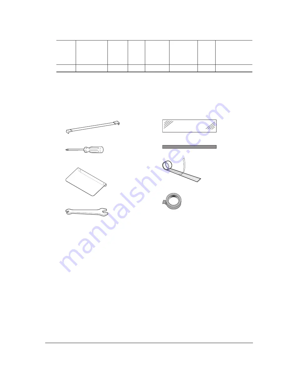
Please make sure that all of the accessories described below are included.
If not, please contact your dealer.

1  Specification

2  Accessories

Heating Element    5 pcs.

Philips Screwdriver    1 pc.

Table    1 pc.

38mm-Width Glass Tape   3 pcs.

Spanner    1 pc.

Sarcon Sheet -W13mm x 370mm    1 pc.

Teflon center-dry tape 40mm x 5M    1 roll

Semi Transparent Tape -W15mm x 3M    1 roll

MS-

350

 NP Operating Instructions Ver 

2

.

01

E

5

Code

Model

Voltage 

V

Power

W

Sealing 

Width mm

Sealing 

Length mm

Weight

kg

Machine 

Dimension mm

W x D x H

-

MS-350 NP

-

1500

10

350

24

525x465x200

Summary of Contents for MS-350 NP Series

Page 1: ...www vanderstahl com Printed AUG 2010 2nd Edition 2 01E Operating Instuructions MS 350 NPSeries MICROCOMPUTER CONTROLLED SEALER FOR STERILIZABLE BAGS MEDICAL POUCH SEALER...

Page 2: ...MS 350 NP Operating Instructions Ver 2 01E...

Page 3: ...ine body 2 The explanations and illustrations in this operators manual utilize the following standard plug configurations most common in Japan However due to the various configurations in use worldwid...

Page 4: ...shing sealing 19 8 11 Counter reset 19 8 12 Power switch OFF 20 8 13 Inspection after operation 20 9 Safety devices and error messages 21 10 Replacing the routine maintenance parts 22 10 1 Preparation...

Page 5: ...Element 5 pcs Philips Screwdriver 1 pc Table 1 pc 38mm Width Glass Tape 3 pcs Spanner 1 pc Sarcon Sheet W13mm x 370mm 1 pc Teflon center dry tape 40mm x 5M 1 roll Semi Transparent Tape W15mm x 3M 1 ro...

Page 6: ...for the MS 350 NP series are described below The machine cannot seal bags which are thicker than that indicated The machine may malfunction if you try to exceed the limits of the machine 3 Replacement...

Page 7: ...e of it Do not remove the control unit unless it is necessary Adhered on the left side of the body frame Adhered at this position of the frame cover 5 Warning caution label location and content Warnin...

Page 8: ...Warning Do not use for packaging liquids Do not splash water on the machine or use machine for packaging liquids since machine is not waterproof There is a danger of electrocution or malfunction of th...

Page 9: ...possibility of burns Do not place hands between the seal jaws pressure lever and seal frame Should the foreign objects such as fingers are clamped between the sealing area and the sealer cannot move...

Page 10: ...and other consumables as well as result in heating element breakage This will lead to decreased work productivity and unnecessary power consumption Set the cooling temperature depending on the film Co...

Page 11: ...ing the power switch to the ON position The heater will only become hot for an instant when the heating process is in operation However after extended periods of use the sealing area may become hot If...

Page 12: ...ndicator lights Mode selection button Allows for changes in the mode setting Numerical setting arrows Auto cycle START STOP ABORT CYCLE Counter and setting display Setting can be increased or decrease...

Page 13: ...MS 350 NP Operating Instructions Ver 2 01E 13...

Page 14: ...ght suitable for your product Install the machine on a flat secure working place Use only as described in this manual There is a risk of danger and malfunctions may result if the machine is used not i...

Page 15: ...le the machine is in the auto cycle interval mode The interval is the time between seals that allows for loading The Auto cycle START STOP button allows you to select between manual touch switch and c...

Page 16: ...ess etc Reset the seal conditions every time you change the bag Setting the various modes Pushing the SET button changes the modes in the following order TEMP DISPLAY HEATING TEMP HEATING TIME COOLING...

Page 17: ...TIME DISPLAY HEATING TEMP PRESS PRESS PRESS PRESS Increase decrese value in the 1 degrees increments Increase decrese value in the 1 degrees increments Increase decrese value in the 0 1 second increme...

Page 18: ...mode Automatic operation takes place based on the preset intervals Place a pouch to the sealing area according to the timing that the pressure lever descends You can deactivate the auto cycle mode by...

Page 19: ...ressure lever returns to the initial position and the sealing is complete If a sealing is not clean enough adjust the heating cooling time or sealing pressure As the sealing operation proceeds the num...

Page 20: ...witch Unplug the power outlet in the case of not using the machine for a while After use please clean up the parts Inspect parts such as Teflon and heating element to make sure that they are not damag...

Page 21: ...heating retaining time When the heating continues over 3 seconds after the heating starts the power switch automatically turns OFF to shut down the heating process When pinching the fingers to the se...

Page 22: ...chine at the optimum condition Replace parts according to the following directions in order to maintain your machine in optimum operating condition Warning Always unplug the power plug before replacin...

Page 23: ...ement How to lift up the pressure lever 1 Loosen the M5x10 frame cover fixing screws and remove the frame cover 2 Loosen the pressure adjusting nut fastening screw do not completely remove it and turn...

Page 24: ...cissors cut the new center dry tape in about the same length as the pressure lever 3 Apply the new center dry tape to the clamping lever starting from the edge Fold the tape along both edges so that t...

Page 25: ...lon center dry tape Attention Make sure that there is no slacking between Screw A 1 and Screw A 2 Essential tools A Philips screwdriver Replace when The temperature sensor is damaged The temperature s...

Page 26: ...heating element It is not necessary to remove the electrode covers 4 Insert a Philips screwdriver into the hole of the electrode cover and loosen screw C The heating element can be removed 5 When moun...

Page 27: ...the Sarcon sheet 1 pc 5 Fold the glass tape along both edges so that the excess tape over the clamping lever adheres to the sides of the pressure lever 6 Adhere the semi trans parent tape on the both...

Page 28: ...emove the 38mm width glass tape adhered on the silicone rubber 2 Using an industrial purpose alcohol etc completely remove the adhesive residues remaining on the metal portion of the pressure lever 3...

Page 29: ...hat fix the wiring 4 When installing a new microswitch push down the pressure lever with your hand Fix the microswith to the position where the microswitch is activated with the clicking sound when th...

Page 30: ...erclockwise to adjust 3 Once the adjustment is made always use the securing screw to secure the pressure adjusting nut 11 Adjusting each part 11 2 Adjust the depth of seal position 11 1 Adjusting the...

Page 31: ...icroswitch Red Red Black Black Black Black Black White White Gray Gray Gray Gray Black Yellow TRIAC Transformer Electrode Heating element Temperature sensor Yellow Yellow Red Red Red Earth Gray 1 2 3...

Page 32: ...lutions Power switch is ON but digital display does not appear Is the electric power dlowing into the sealer Set properly so electrical power will ow Is the power plug fully plugged in Insert the powe...

Page 33: ...or Sarcon sheet Heating element bends at the center Is the electrode damaged Replace the electrode Sealing is not clean Are the Te on glass tape sarcon sheet and silicone rubber white damaged Replace...

Page 34: ...he pressure referring to 11 1 Adjusting the seal pressure Do you use the extension cord Are you using the heating element speci ed by Fuji Impulse Heating element may be broken Turn OFF the power swit...

Page 35: ...itch on with pushing SET button Input 4 digit password 0000 appears on the display and the left end 0 is flushing on and off Select the number by UP DOWN button and decide it by SET button Repeat the...

Page 36: ...0 appears and the left end number is flushing on and off Select the number by UP DOWN button and decide it by SET button Repeat the same process for all 4 digit When the password is correct When the p...

Page 37: ...please consult the exploded view diagram spare parts list on the following pages and provide both the part name and code number to your local dealer Exploded View Spare Parts list MS 350 NP Operating...

Page 38: ...a b A MS 350 NP Exploded View E Type MS 350 NP 38...

Page 39: ...langer stopper sponge 2pcs set 28 492800 Shock absorber with nut 1 pc 29 421700B H type electrode 2pcs set 30 421702B Terminal cover 2pcs set 32 493201 Frame cover 1 pc 33 493300 Microswitch 1 pc 34 S...

Page 40: ...Y6602 AUG 2010 2nd Edition MS 350 NP Operating Instructions Ver 2 01E...

Reviews: