


DSBA3400 • Rév. 09/06/2020
46
EN
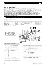
The terminal temperature can reach 90°C
The used wires must be rigid (feedback voltages : 4 to 250V AC/DC)
For a use with a long power supply wiring, the induction current generated by the wires mustn't be higher than 1mA.
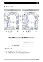
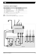
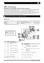
GFS: description & electric diagram
GFS model includes a BBPR unit and 3 positions
Rep.
Designation
Rep.
Designation
FC0
Open limit switch
FC1
Auxiliary limit switch 1
FCF
Close limit switch
FC2
Auxiliary limit switch 2
FCIO
Intermediate open limit switch
FC3
Auxiliary limit switch 3
FCIF
Intermediate close limit switch
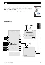
D3/D4 Failure report Terminal strip (24V DC / 3A max)
SNAA710000
FCF
FC0
+
—
~
~
FC2
FC1
FCIF
FCIO
FC3
A
B
F
EED
BA
CK
F
C
1
F
EED
BA
CK
F
C
2
F
EED
BA
CK
F
C
3
COMMON FC2
COMMON FC3
Feedback
COMMON FC1
100 V-240 V 50/60 Hz (100 V-350 V DC)
24 V-30 V 50/60 Hz (24 V-48 V DC)
TP/PE
Power supply
3
2
1
4
N / -
I
F
O
Ph / +
65
66
F+ F-
Ch
arge
report
Attery charged
contact closed
T+
D3
D4
F
a
ilu
re
report
A
0
B
RS485
A
C
B
17
18
9
6
8
4
F9
F4
Battery block
17
18
F6 F7 F8
F8
F6
F7
A
M
BBP
R c
h
a
rgin
g
/c
ont
rol boa
rd
SN
BA
140
00
0
F+ F- T+
red Black/white
white
Noir
Blanc
Rouge


