Valor Ultimate Installer'S Manual Download Page 8

must be 

not less than the dimension shown in figure 3.

The current versions of BS1289 and BS EN 1806 recommend that there should be an air
space or insulation between the flue blocks and the plaster because heat transfer may
cause cracking on directly plastered flues. However, generally this appliance is suitable
for installations under all circumstances unless there is a history of cracking problems.
Remember that faults such as cracking may be caused by poorly built and restrictive
flues, e.g. mortar extrusions, too
many bends, flue heights below
three metres, restrictive
terminations, etc.

3.2.4

If the fireplace opening is

greater than the acceptable
dimensions given in this guide, do
not use the back of a fire surround
or marble to reduce the opening.
This may cause cracking of the
surround back or marble.

3.3

The following flues are

suitable:

225mm x 225mm

conventional brick flue.  
If a flue liner is used, it must be a
minimum of 125mm diameter.
The liner must be sealed to the
surrounding area above the
fireplace opening and to the top of
the chimney. An approved
terminal must be fitted.

200mm diameter factory made

insulated flue manufactured to BS
4543.

A properly constructed precast flue conforming to B.S 1289 or BS EN 1806.

A flue pipe with a minimum diameter of 175mm. See B.S 6461 Part 1 for suitable

materials. Metal flue pipes must comply with B.S 715.

Single wall, twin wall or flexible flue liner of minimum diameter 125mm. The

materials used are stainless steel or aluminium as specified in B.S. 715.

3.3.1

The minimum effective height of the flue must be 3m.

3.3.2

The flue must be clear of any obstruction and its base must be clear of debris.

Page 8

INSTALLER GUIDE

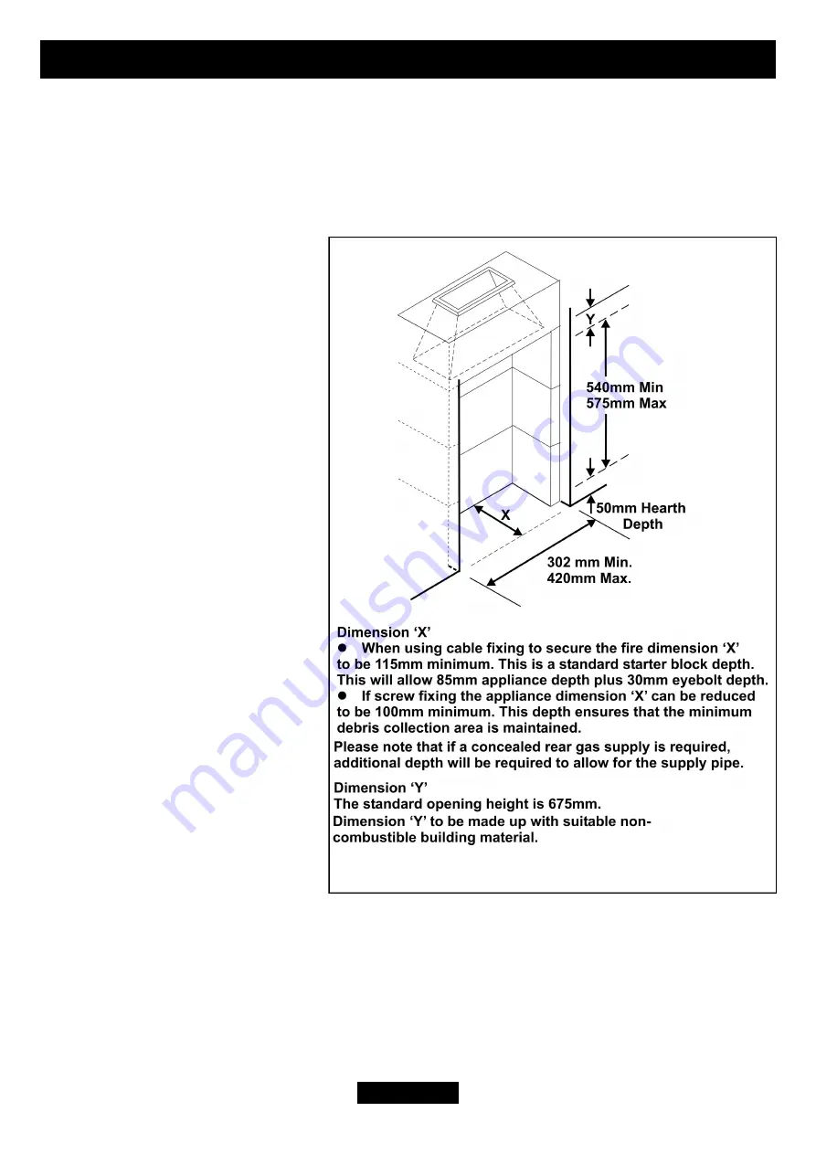
Figure 3. Pre-cast Fireplace

Summary of Contents for Ultimate

Page 1: ...National call rates apply in the United Kingdom In the Republic of Ireland call 0044 08706 061 065 INSTALLER Please leave this guide with the owner Valor Heating Ultimate Model 717 GC No 32 032 52 INS...

Page 2: ...a member of the Society of British Gas Industries which works to ensure high standards of safety quality and performance Careful Installation Valor is a CORGI registered company All our gas fires must...

Page 3: ...hecks 22 10 2 1 Lighting the burner 22 10 2 2 Operating the burner 22 10 3 Reference Pressure Check 23 11 FITTING THE FRONT SURROUND 23 12 CERAMIC COALS INSTALLATION 24 13 FIREFRONT CASTING8INSTALLATI...

Page 4: ...ance When lifting always keep your back straight Bend your legs and not your back Avoid twisting at the waist It is better to reposition your feet Avoid upper body top heavy bending Do not lean forwar...

Page 5: ...or the disposal of industrial waste Protective clothing is not required when handling these articles but we recommend you follow the normal hygiene rules of not smoking eating or drinking in the work...

Page 6: ...the following British Standards BS 715 BS 1251 BS 1289 Part 1 BS EN 1806 BS 4543 Part 2 BS 5440 Part 1 BS 5440 Part 2 BS 5871 Part 1 BS 6461 Part 1 BS 6891 In England and Wales the current edition of...

Page 7: ...nce from the base of the fireplace opening in the wall to the finished floor level is at least 72mm 3 2 2 To a fireplace incorporating a metal flue box conforming to BS715 with a minimum internal dept...

Page 8: ...ng This may cause cracking of the surround back or marble 3 3 The following flues are suitable 225mm x 225mm conventional brick flue If a flue liner is used it must be a minimum of 125mm diameter The...

Page 9: ...uel the flue must be swept clean prior to installation All flues should be inspected for soundness and freedom from blockages 3 8 If the fireplace opening is an underfloor draught type it must be seal...

Page 10: ...a bath or shower or where steam is regularly present 3 14 An extractor fan may only be used in the same room as this appliance or in any area from which ventilation for the appliance is taken if it d...

Page 11: ...t touch the surround See figure 4 We suggest that the actual surround is used as a template to mark the area for combustible cladding removal and that this area is increased by at least 2mm all round...

Page 12: ...shut the appliance down if an unacceptable amount of harmful products of combustion accumulate Under no circumstances should the A S D be altered or bypassed in any way Only a genuine manufacturers re...

Page 13: ...surround 1 Firefront casting 1 Front cover casting Remove all the items carefully to prevent damage Take special care when handling the ceramic components Some items may be contained in the packaging...

Page 14: ...ogether with secondary fixing to the fireplace floor The methods are detailed in section 9 of this manual Before selecting the retention method consult with the customer Method 2 is provided for insta...

Page 15: ...ng to install it is worth checking that the ignition system performs satisfactorily Set the control knob to the off position Depress the control knob and rotate it anticlockwise to the pilot ignition...

Page 16: ...n by the Debris catchment area Note that the areas are different for fireplaces with conventional brick flues and precast flues 2 Place the template on the fireplace floor printed side upward with the...

Page 17: ...n seals to the bottom edges of the convection box side flanges See figure 9 IMPORTANT Before continuing with the installation of this gas fire the aeration setting on the burner must be checked The ae...

Page 18: ...pliance is supplied with a flue restrictor for use where the flue draught is excessive The restrictor must not be fitted where a precast flue or a 125mm flue liner is used For flue liners greater than...

Page 19: ...rawlplug into each hole 6 Place the convector box back in position in the fireplace 7 Fit a woodscrew through each hole in the convector box flanges and tighten to seal the box to the fireplace surrou...

Page 20: ...the holes See figure 15 Give the cables a pull so that they grip against the convection box flanges 6 Thread the cables through the upper eyebolts in the rear wall and then through the lower eyebolts...

Page 21: ...e tension on the cables by slackening the screws and turning the hexagonal adjusters fully anticlockwise The convection box should then automatically realign itself Pull each cable taut again and push...

Page 22: ...the pilot ignition position A click will be heard as the integral piezo operates A spark should be seen between the electrode and pilot tip 2 Turn the control knob clockwise to the Off position Repea...

Page 23: ...checking turn off the appliance Remove the pressure gauge and replace the test point sealing screw 3 Relight the appliance Turn to the maximum output position and test around the sealing screw for gas...

Page 24: ...e amount of movement will be negligible See figure 22 2 Place the front base coal in the firebox with its bottom front locating over the front rim of the firebox Pull the coal forward so that it locat...

Page 25: ...n the front and rear base coals as shown in figure 25 The letter B should be upright 5 Place a type A coal between the front and rear base coals with the letter A upright The top of the coal should re...

Page 26: ...sting so that it rests on the hearth See figure 29 Black chrome front casting Place the fire front casting in front of the appliance 2 Place the bottom front cover casting in position below the fire f...

Page 27: ...htly to get past the pilot ignition position The main burner should now light Depress the control knob slightly to release from the HIGH position and turn back clockwise to LOW While turning the burne...

Page 28: ...n repeat the test If the smoke is still not drawn into the appliance inspect the sealing to the fireplace surround If the sealing is satisfactory but the appliance is installed with the flue restricto...

Page 29: ...e fire 3 Explain to the customer that the appliance has a flame failure and spillage monitoring system Point out the explanation of this system shown in the owner s guide Advise that if the fire goes...

Page 30: ...let T connector incorporates an isolating valve It is recommended that at least once a year the appliance is disconnected and the fireplace opening checked and cleared of any debris This product uses...

Page 31: ...st the aeration setting loosen the two aeration shutter screws slide the aeration shutter to the position shown in figure 31 and tighten the fixing screws 17 2 To Remove the Fire Front Surround 1 Remo...

Page 32: ...he pilot unit 4 Detach the thermocouple from the gas valve 5 Detach the electrode lead from the underside of the electrode tab 6 Remove the two screws securing the pilot unit See figure 34 7 Refit in...

Page 33: ...t 10 Remove the gas valve 11 Refit in the reverse order 17 6 To Replace the Burner See figure 36 1 Remove the burner unit See section 17 3 2 Support the elbow injector and unscrew the injector nut 3 R...

Page 34: ...fire retention is as method 1 See section 9 1 of installation instructions remove the screws If the fire retention is as method 2 See section 9 2 of installation instructions slacken the hexagonal ad...

Page 35: ...Gas tap spark generator 1 3002983 C Spark generator and circlip 1 5108923 D Control knob 1 0545979 E Pilot unit For Natural Gas Appliances Pilot injector RBM 180 02 For Propane Appliances 1 3002988 51...

Reviews: