5555
2.
OPERATION
2.1
The pilot may be left alight (please not though, that it consumes approximately 1/3kW). The pilot should be
turned off if the premises are to be left unoccupied for a lengthy period.
2.2
The flame sensing & flue ventilation monitoring system
For your safety, this appliance is fitted with a system which will automatically shut off the gas supply to the fire
•
if the pilot burner flame goes out
•
if the flue is blocked
The system includes a probe which senses the heat from the pilot burner flame. If this probe is cool, the system will
prevent any gas flow unless the control knob is kept held down (See the following lighting instructions.
The system also includes a detector which will shut off the gas supply if the
flue is faulty causing incorrect ventilation of the exhaust fumes.
If the flames go out, or if for any reason the fire is turned off, always wait at
least 3 minutes before attempting to relight.
If the monitoring system starts to shut off the gas frequently please get
expert advice.
In the United Kingdom call the Valor AdviceLine on 0345 626341
(local call rates apply).
2.3
To light the pilot
Warning
If the pilot flame is extinguished either intentionally or unintentionally, do not attempt
to relight the gas until at least 3 minutes have elapsed.
2.3.1
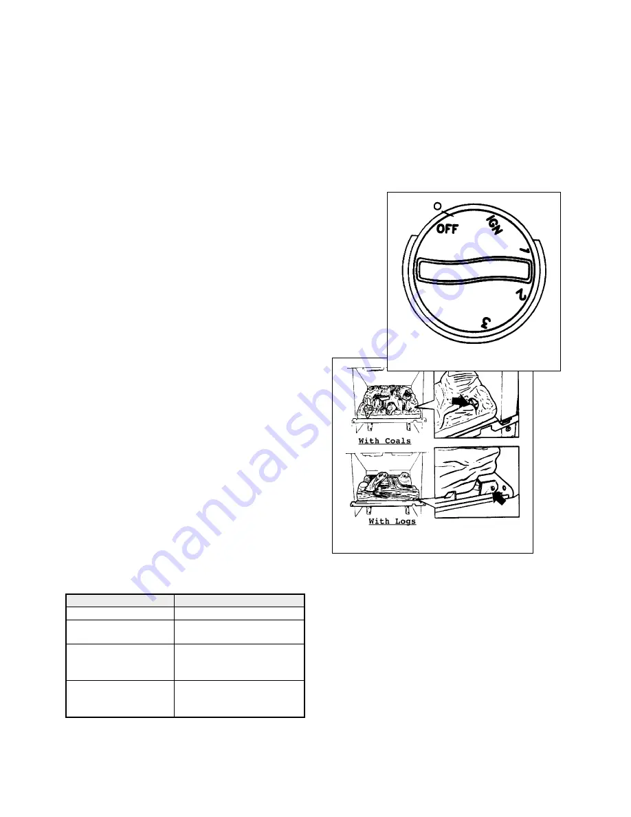
Depress the control knob. Turn anticlockwise until resistance is
felt just before the IGN position.
Keep the knob depressed for a few seconds to allow the gas
to flow to the pilot then, keep the knob depressed and turn to
the IGN position. A spark should be produced which should
ignite the pilot gas.
The pilot flame can be seen by looking through the gap at the
front corner of the fuel effects - see figure 3.
2.3.2
In the unlikely event that the pilot can not be lit after
repeated attempts to producing a spark, a lighted spill can be
used as described in section 2.7 of these instructions.
2.3.3
When the pilot is alight, keep the control knob
depressed for a few seconds to prevent the flame supervision
device from shutting off the gas supply while its probe
warms up, as explained above, then release it. If the pilot
does not remain alight turn the knob back to OFF, wait a few
seconds and repeat the lighting sequence.
2.4
To select burner setting
When the pilot is alight, partially depress the knob and turn
to the setting you prefer. The settings are as follows:-
Control Knob Setting
Burner Appearance
IGN
Pilot burner only on
1
Pilot burner on
Front burner on low
2
Pilot burner on
Front burner on low
Rear burner on high
3
Pilot burner on
Front burner on high
Rear burner on high
2.5
Please note
:
it is recommended that the fire be set at position 3 for the first 10 minutes after lighting to warm up the chimney and
so obtain full efficiency quickly.
Fig. 3 Pilot Viewing Opening
Fig. 2 Control


