background image


32 


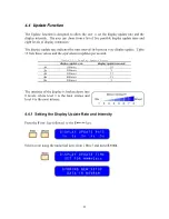
Select an intensity level using the numerical keys from 1 thru 8 and press 

E

NTER


The  values  are  stored  in  memory  and  the  instrument  will  automatically  return  to  the 
previous mode. 
 

4.5  Run/Hold Function 

 
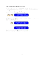
The Run/Hold function of the 4176 can be configured in three different ways: 
 

HOLD 

–  Pressing  the 

R

UN

/

H

OLD

  key  will  freeze  the  readings  on  the  display.    The 

function  window  of  the  screen  will  flash  “HOLD”.    To  exit  the  hold  state,  press  the 

R

UN

/

H

OLD

 key again. 


PKHI 

– Pressing the Run/

H

OLD

 key will activate the Peak-Hi state.  The readings on the 

display will only increment therefore showing the maximum value measured.  While in 
Peak-Hi  state,  the  function  window  of  the  screen will flash “PKHI”.  To exit this state 
press the 

R

UN

/

H

OLD

 key again. 


PKLO

 - Pressing the Run/

H

OLD

 key will activate the Peak-Lo state.  The readings on the 

display  will  only  decrease  therefore  showing  the  minimum  value  measured.    While  in 
Peak-Lo state, the function window of the screen will flash “PKLO”.  To exit this state 
press the 

R

UN

/

H

OLD

 key again. 


Summary of Contents for 4176

Page 1: ...Operation Manual Model 4176 Programmable Micro Ohmmeter VA L H A L L A S C I E N T I F I C Need Help Call 800 548 9806 www valhallascientific com 2015 Valhalla Scientific Inc All Rights Reserved...

Page 2: ...change any or all specifications without notice The warranty period for this instrument is stated on your invoice and packing list Please refer to these to determine appropriate warranty dates Valhall...

Page 3: ...the manual is revised Updates which are issued between editions contain replacement pages to correct or add additional information to the current Edition of the manual Whenever a new Edition is create...

Page 4: ...lt Alternating current AC Direct current DC Calls attention to a procedure practice or condition that could p o s s i b l y c a u s e d a m a g e t o equipment or permanent loss of data WARNING Calls...

Page 5: ...procedures involving cover or shield removal unless you are qualified to do so DO NOT operate damaged equipment Whenever it is possible that the safety protection features built into this product hav...

Page 6: ...pter lists and describes all the optional equipment and accessories available for this model CHAPTER 6 REMOTE INTERFACE This chapter illustrates the remote capabilities and explains how to send comman...

Page 7: ...TCM Receptacle and LEDs 13 3 2 6 HLC LEDs 14 3 2 7 Remote LED 14 3 2 8 Source and Sense Binding Post 14 3 3 REAR PANEL 15 3 3 1 Line Voltage Switch 15 3 3 2 Fuse Holder 16 3 3 3 Power Connector 16 3...

Page 8: ...2 1 The GPIB interface capabilities 45 6 2 2 Notes for GPIB installation 46 6 2 3 Computer s Connection 46 6 2 4 The GPIB connection testing 46 6 3 CONNECTING THE 4176 VIA RS232 INTERFACE 47 6 3 1 The...

Page 9: ...RCE DETAILED CIRCUIT DESCRIPTIONS 80 10 5 1 Power Supplies 80 10 5 2 Constant Current Source 81 10 6 MICRO CONTROLLER BOARD DETAILED CIRCUIT DESCRIPTIONS 82 10 6 1 Micro Controller 82 10 6 2 Over Volt...

Page 10: ...the factory Even if the instrument appears undamaged it may have suffered internal damage in transit that may not be evident until the unit is operated or tested to verify conformance with its specif...

Page 11: ...s of two brackets plus 4 flat head screws The brackets are easily installed on the front end of each side rail as show in drawing 4176 xxx in chapter 11 The kit is listed in chapter 5 as Option R The...

Page 12: ...a ground connection If power is provided through an extension cable the ground connection must be continuous Any discontinuity in the ground lead may render the unit unsafe for use The testing of ind...

Page 13: ...A 20k 30 000k 1 10 A 1 Current source is 1 absolute accuracy Table 3 Standard Measurement Mode Accuracy Accuracy2 of reading of range Range 24 hours 1 Year Temperature Coefficient3 20m 0 006 0 012 0 0...

Page 14: ...02 0 07 0 001 0 02 0 07 0 001 20 0 02 0 07 0 001 0 02 0 07 0 001 200 0 02 0 07 0 001 0 02 0 07 0 001 2k 0 02 0 07 0 001 0 02 0 07 0 001 20k 0 02 0 07 0 001 0 02 0 07 0 001 4 The accuracy specification...

Page 15: ...h to Low Test Current Compliance Voltage 5V minimum Settling Time 300 milliseconds 2 4 Environmental and Power Requirements Power Supply 115VAC or 230VAC 10 50Hz to 400Hz 25VA max Operating Temperatur...

Page 16: ...measurements it is useful to describe the sections of the front and rear panel of the 4176 3 2 Front Panel The front panel of the 4176 can be broken down into eight parts In Figure 5 you can see the r...

Page 17: ...cientific Logo If a function is activated this section of the display will alternate between the Logo and the abbreviated function name Figure 6 Display Window sections The display is also used to pro...

Page 18: ...w the setting information for all of the standard or optional remote interfaces 3 RUN HOLD The RUN HOLD key is used to switch between run and hold state Also used to select the hold configuration 4 PR...

Page 19: ...connector in the receptacle Figure 9 Temperature sensor TCM LEDs and Receptacle The TCM feature of the 4176 arithmetically calculates the resistance value to display utilizing the ambient temperature...

Page 20: ...l state will receive commands only from the front panel keys 3 2 8 Source and Sense Binding Post Connections to the 4176 are made via the front panel source sense terminals which consist of two red an...

Page 21: ...l for addendums that reference the particularities of your model We will now outline the use of each of the rear panel controls and connectors Figure 10 4176 Standard Rear Panel 3 3 1 Line Voltage Swi...

Page 22: ...ed to three relays which are active only when the HLC mode is selected According to the result of the comparison one of the relays will have its contacts close while the remaining two relays will have...

Page 23: ...cific pin functions of the serial connector may be necessary for certain applications table 7 lists the pin assignment for the RS 232 connector Pin Pin Function 1 No connection 2 Receive Data RxD inpu...

Page 24: ...e display you should see the following messages Figure 11 Power On Display Messages When the power on routine is finished the ohmmeter will beep twice By design the standard measurement mode the auto...

Page 25: ...tion of the ground maker on the plug Marked side of each banana jack is connected to the current terminals see table 9 Table 9 Connecting test leads to the ohmmeter Lead 1 Connect between SENSE HI and...

Page 26: ...face of the probe is in full contact with the surface of the load Press the second probe against the surface at the oppose side of your load making sure that the surface of the probe is in full contac...

Page 27: ...d Safe Mode When the value of the load exceeds the range limit the instrument will be in an Overload state In cases of overload the display will repeatedly flash the word OVERLOAD If this occurs selec...

Page 28: ...ad by several orders of magnitude The 4176 bypasses this potential error source by providing two terminals of constant current and an additional two terminals for high impedance voltage measurement Th...

Page 29: ...is equal to the temperature coefficient of the material multiplied by the variation of temperature Expressed in terms of the resistance 0 0 0 T T R R R or 0 0 1 T T R R To better understand our uses o...

Page 30: ...ation will also be necessary if the sensor is purchased as a single item The TCM calibration routine is describe in section 2 4 of this chapter 4 2 2 TCM ON The TCM mode can be selected from the front...

Page 31: ...ot need to be repeated every time the TCM mode is selected The configuration that is selected or the custom values inputted will be set as default 1 ENTER sets the CU20 configuration 2 ENTER sets the...

Page 32: ...ave typed Check the value and press enter to confirm If the value is incorrect press clear to return to the input screen Using the numeric keys input a value for the reference temperature followed by...

Page 33: ...ure Compensator Calibration must be done in a temperature controlled area When the readings stabilize the instrument will automatically skip to the next screen Using the numeric keys input a value for...

Page 34: ...to implement an automated batch sorting system for components or products operate counters sound alarms or shut off a process Resistors transformers strain gauges thermocouples and thermistors are a...

Page 35: ...200 100 00 200 00 2k 1 0000k 2 0000k 20k 10 000k 20 000k To set your custom readings simply select the range that better fits your load and follow this procedure Using the numerical keys enter the va...

Page 36: ...00 2k 1 0000k 2 0000k 20k 10 000k 20 000k 4 3 3 HLC ON To start working with the HLC mode simply select the correct range for your application and press the HLC key The screen will briefly display HLC...

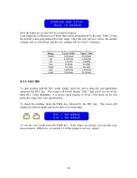
Page 37: ...y update Table 13 lists these values and the equivalent in updates per second Table 13 Display Update Rates display update rate display updates second 1s 100msec 10 2s 200msec 5 3s 300msec 3 3 4s 400m...

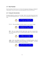
Page 38: ...exit the hold state press the RUN HOLD key again PKHI Pressing the Run HOLD key will activate the Peak Hi state The readings on the display will only increment therefore showing the maximum value mea...

Page 39: ...llow these simple steps to configure the function Press the FUNC key followed by the RUN HOLD key Using the numerical keys from 1 thru 3 select the action that you wish the Run Hold function to use an...

Page 40: ...transmits one reading as it is displayed on the ohmmeter s screen LOG When the Print key is pressed the instrument transmits continuously the measurements at a rate equal to the display update rate9 P...

Page 41: ...Follow these simple steps to configure the function Press the FUNC key followed by the PRINT key Using the numerical keys from 1 thru 3 select the action that you wish the Print Log function to use an...

Page 42: ...lowing function keys To exit the View mode press the VIEW key at ay time UPDATE The screen displays the display update rate and intensity settings HLC The screen displays the HLC limits for the range...

Page 43: ...creen will display the temperature coefficient and temperature reference value set for the TCM mode AUTO RNG The screen will display the auto range status on or off and the range that is in use CAL Th...

Page 44: ...nge including Auto to return to measurement mode This is so that the user can be aware that an overload has occurred so that the cause maybe investigated if necessary 4 8 1 Enabling SafeMode To enable...

Page 45: ...ar panel 50 pin connector All outputs are TTL compatible levels with a drive capability of 1 LS load Also refer to chapter 7 5 1 2 GPIB The Valhalla 4176 comes standard with a RS 232 interface Also av...

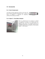
Page 46: ...nsate for temperature variations when testing any material 5 2 2 Option R Rack Mount Adapter The 4176 ohmmeters may be mounted in a standard 19 equipment rack using a set of optional rack ears Option...

Page 47: ...recommended general purpose lead set for most applications Option KCS Gold Plated Clips Option KCS are gold plated alligator clips used on the Option K lead set for 4 wire measurements of smaller com...

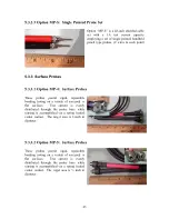
Page 48: ...ion MP 1 is a 48 inch shielded 4 wire Kelvin cable set with a 1A test current capacity employing a set of Kelvin Micro Probes The probes are equipped with spring loaded stainless steel tips with 0 05...

Page 49: ...ding testing on a variety of screened or flat surfaces Test current is evenly distributed through the probe base while sensing is accomplished via a spring loaded center contact The target area is 1 i...

Page 50: ...stacking banana plugs This cable may be used for voltage and current connections to the ohmmeter 5 3 4 2 Option SL 48 Low Thermal Leads Option SL 48 is a 48 shielded lead set terminated in gold plated...

Page 51: ...s SH1 Source Handshake The 4176 can transmit multilane messages across the GPIB AH1 Acceptor Handshake The 4176 can receive multilane messages across the GPIB T6 Talker Talker interface function inclu...

Page 52: ...of GPIB system 6 2 3 Computer s Connection A personal computer with a GPIB card is the essential facilities in order to operate the 4176 via GPIB interface The connections between power supply and co...

Page 53: ...ocated on the rear panel Table 14 shows the 9 pin connector Female with its pin number assignments Figure 17 shows the wiring configuration for DB9 to DB9 When the 4176 is set up with a RS232 interfac...

Page 54: ...iguration Pin Pin Function 1 No connection 2 Receive Data RxD input 3 Transmit Data TxD output 4 No connection 5 Signal Ground GND 6 No connection 7 No connection 8 No connection 9 No connection Figur...

Page 55: ...on the 4176 III Turn on the 4176 IV Turn on the computer 6 3 4 Checking Connections If you want to test whether the RS232 connection is working or not you can send a command from computer For instance...

Page 56: ...uffer and delivered As for query command the return message of the instrument is also added a LF for PC to judge message terminator 6 5 2 Entering Commands The standards that govern the command set fo...

Page 57: ...hen a valid printable character is received and is exited with the LOCAL front panel key or LOCAL command 6 6 1 Command Index CLS COMMAND 53 IDN QUERY 57 RST COMMAND 63 STB QUERY 64 SYST ERR 52 ADDRS...

Page 58: ...memory Syntax ADDRS decimal address Response crlf Parameter Address number 1 32 decimal Example ADDRS 7 crlf ADDRS crlf 7 crlf Power on default 10 Note Value can be saved to non volatile memory with S...

Page 59: ...s on the relays outputs See chapter 7 for BCD connector pin outs and relay descriptions BCD QUERY Responds with BCD mode on or off Syntax BCD Example BCD crlf ON crlf Response ON or OFF Power on defau...

Page 60: ...noisy FAULT COMMAND Sets an alarm fault to watch the system react Syntax FAULT Hexadecimal number FAULT_ALARM_NO_FAULT 00 FAULT_ALARM_OVER_TEMP 01 Internal temperature too high FAULT_ALARM_CAL_LIMIT 0...

Page 61: ...ow on space in transmit buffer FAULT_ALARM_TXBUF_FULL 20 Serial transmitter buffer full FAULT_ALARM_RCVBUf_FULL 40 Serial receiver buffer full FAULT_ALARM_NVRAM 80 NV RAM fault Power on default 00 HLC...

Page 62: ...d point Ohm value for current range 1 0000 for 1 Ohm in the 2 Ohm range and 100 00 for 100m Ohm in the 200m Ohm range This command reads the value from RAM memory only If you have used the HLCHI comma...

Page 63: ...e HLCLO command to write a HLC value it will be different than the value stored in non volatile memory if the SAVSETUP command has not been sent Send RANGE command before sending this command Power on...

Page 64: ...KEY_UNKNOWN KEY_UPDATE KEY_1 KEY_HLC KEY_2 KEY_ADDR KEY_3 KEY_RUNHOLD KEY_4 KEY_PRINT KEY_5 KEY_TCM KEY_6 KEY_AUTO_RNG KEY_7 KEY_CAL KEY_8 KEY_BCD KEY_9 KEY_VIEW KEY_0 KEY_DISPLAY KEY_1 KEY_mk KEY_DP...

Page 65: ...KEY_UNKNOWN KEY_UPDATE KEY_1 KEY_HLC KEY_2 KEY_ADDR KEY_3 KEY_RUNHOLD KEY_4 KEY_PRINT KEY_5 KEY_TCM KEY_6 KEY_AUTO_RNG KEY_7 KEY_CAL KEY_8 KEY_BCD KEY_9 KEY_VIEW KEY_0 KEY_DISPLAY KEY_1 KEY_mk KEY_DP...

Page 66: ...inguish the REMOTE LED and transition the device to the front panel local user mode LOG COMMAND Selects LOG mode on or off Syntax LOG ON or OFF 0 synonomous with OHMS Example LOG ON 0 crlf space or co...

Page 67: ...000 crlf on 20m or 20k Ohm ranges Response 20 000 crlf Power on default 0 000 Note For Scientific notation Engineering format use RDNG OPT QUERY Returns the option text strings factory installed on me...

Page 68: ...e RDNG crlf 2 4321e 1 crlf on 20 000 Ohm ranges Response value in reduced engineering notation crlf Power on default 0 000e 0 CAUTION Will not work if the transmit interrupt happens to be busy with a...

Page 69: ...g it Expect a 500ms delay after receiving the linefeed before transmitting next command RST COMMAND Sets buffers to power on default Syntax RST crlf Response crlf Remote command buffer Serial I O hist...

Page 70: ...AM 4 CMD_INVALID_PARAM 8 CMD_MODE_OFF 16 CMD_INCORRECT_NUMBER_PARAMS 32 64 128 CMD_CALLAREALPGMR Power on default 0 Note After a command or query with or without a response the STB query responds with...

Page 71: ...h TCM mode on or off Syntax TCM Example TCM crlf ON crlf Response ON or OFF Power on default OFF Send this date after the calibration is complete followed by a SAVESETUP to store in EE memory TST QUER...

Page 72: ...mation and overload A run hold line is also provided to halt the 4176 The signals are TTL compatible V 8 0 and V 4 2 1 and will drive 1 LS TTL load 7 2 BCD Pin Assignments DATA This is the BCD coded d...

Page 73: ...R2 R1 R0 Ranges OFF 0 0 0 0 20m 0 0 0 1 200m 0 0 1 0 2 0 0 1 1 20 0 1 0 0 200 0 1 0 1 2k 0 1 1 0 20k 0 1 1 1 OVERLOAD PIN 12 This is a logic 1 when the data on the lines above is an overload indicatio...

Page 74: ...23 80 5 100 24 200 6 400 25 800 7 1000 26 2000 8 4000 27 8000 9 10000 28 20000 10 R0 29 R1 11 R2 30 R3 12 OVERLOAD 31 NC 13 NC 32 AVDD 14 AVDD 33 AVDD 15 AVDD 34 AVDD 16 AGND 35 AGND 17 AGND 36 AGND...

Page 75: ...l be used 0 01 0 1 1 10 100 1k and 10k 2 DC voltage standard capable of outputting 10mV 300mV and 1V Valhalla Model 2701C is suitable for the task 3 Four wire test lead set 4 Precision Digital Voltmet...

Page 76: ...board All three calibrations must be performed for a complete calibration of the 4176 8 4 1 1 Sense Calibration Step 1 Press the FUNC key followed by the CAL key The screen will display the following...

Page 77: ...he zero cal for all the ranges the screen will prompt the following message Step 4 Apply 10mV using the voltage standard and press ENTER to start the 20m range voltage calibration Press the CLEAR key...

Page 78: ...R button if you wish to return to the previous screen This step will perform the voltage calibration from 200m range to the 20k range When the instrument has completed the 300mV cal the screen will pr...

Page 79: ...the value of the load Step 11 Select the 20 range Step 12 Connect the 4176 to a 10 standard resistor Step 13 Adjust RV4 for a display reading equal to the value of the load Step 14 Select the 200 rang...

Page 80: ...he CAL key again to enter the ohms cal mode Step 5 Press the FUNC key to skip zero volts cal Step 6 The screen should display Step 7 Press ENTER to continue Step 8 Once the 10mV cal is complete the sc...

Page 81: ...lution Do not use abrasive cleaners on the ohmmeter The front panel may be cleaned with a soft cloth and a Windex type cleaner if required Do not use petroleum based cleaners on the front panel If req...

Page 82: ...due to the very high impedance to line voltage exhibited by the load causing an excessive amount of noise pick up This effect can be significantly reduced by using fully shielded cables It may also be...

Page 83: ...ecked As it is not possible to anticipate all failure modes of the ohmmeter servicing personnel should become familiar with this chapter of the manual to gain a complete understanding of the internal...

Page 84: ...is passed through the load to develop a voltage across it The value of this current for each range is indicated on the front panel of the instrument Micro Controller Board 834u 700 This is the central...

Page 85: ...status of the temperature compensation mode 10 4Troubleshooting Use the following guidelines to determine in which circuitry that fault originates If the fault occurs on one range only then the fault...

Page 86: ...he micro controller and the remaining circuitry All of these supplies are similar in design A secondary winding of the transformer T1 provides the basic AC voltage from which the DC supply will be pro...

Page 87: ...stage is used to convert the 6 95 VDC reference voltage to the negative 1 volt reference required by the current source This voltage level can by checked by measuring the voltage across TP10 and TP9...

Page 88: ...l conversion on the voltage across the load Also all other processes such as range selection HLC relay switching LEDs activation and so on Refer to schematic 834u 070 sheet 1 10 6 2 Over Voltage Prote...

Page 89: ...5V Reference U2 is a precision 2 5V reference used by the micro controller during the analog to digital conversion Refer to schematic 834u 070 sheet 1 10 6 6 Download Normal Switch J4 is the switch th...

Reviews: