background image


5-7. 

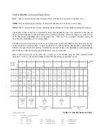
Remote and Local States 


¾

 Local State


When the 4300B is in the "local" state the REMOTE indicator on the front panel is extinguished and full 
manual control as described in Section 4 may be performed.  The user should also note that the 4300B will 
ignore commands from the GPIB while in the local state. 
 
The 4300B automatically powers-up in the local state.  Other methods for placing it in the local state are by 
cycling power or by sending a 

return to local

 (RTL) command over the bus.  This is done in HP Basic using 

the command: 

LOCAL 712


To ensure compatibility with all controllers, the 4300B may also be returned to the local state by sending it the 
code:   

L


¾

 Remote 

State


In this state the REMOTE indicator on the front panel is illuminated and all controls on the front panel are 
disabled except the power switch. 
 
The remote state may only be entered via the bus.  If the 4300B receives its listen address while the REN line 
is asserted, it will enter the remote state.  Placing the instrument into remote is an easy way of verifying that all 
connections and address selections have been done properly.  This may be accomplished in HP Basic using 
the command:   

REMOTE 712

   The 4300B should enter the remote state and illuminate the REMOTE 

indicator.  Verify that no other device on the bus was affected by execution of this command. 


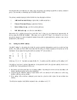
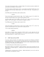
5-8. 

Reading the Display Data 


The resistance data on the 4300B's display is always available to be read by the system controller.  The 4300B 
does not require that a query or any other command be issued in order to retrieve it.  Also, the 4300B does not 
need to be in REMOTE in order for the display to be read.  Retrieving the data will clear the reading buffer.  
The controller must then wait until the next update of the A-to-D converter before a new value becomes 
available.  Data may be read at the rate of 2½ readings per second for a 4300B, or 12½ readings per second for 
a 4350ATE. 
 
The fact that the readings are always available simplifies measurement retrieval.  Every time the system 
controller polls the 4300B's address, an instantaneous resistance value is returned corresponding to the 
displayed value. 
 
The following program shows an example of retrieving a resistance measurement from the 4300B.  The 
program is written in HP Basic.  If you are using a programming language or package other than HP Basic, 
consult your Programmer's Manual for the correct command syntax.  The 4300B is assumed to be at address 
12. 


  10 

ENTER 

712;A$ 


  20 

PRINT 

A$ 


  30 

GOTO 

10 


  40 

END 


Summary of Contents for 4300B

Page 1: ...Operation Manual Model 4300B Digital Micro Ohmmeter VA L H A L L A S C I E N T I F I C Need Help Call 800 548 9806 www valhallascientific com 2015 Valhalla Scientific Inc All Rights Reserved...

Page 2: ...nty period for this instrument is stated on your invoice and packing list Please refer to these to determine appropriate warranty dates We will repair or replace the instrument during the warranty per...

Page 3: ...rements 12 4 3 SETTING VOLTAGE AND TEST CURRENT 12 4 4 CHARGING INDUCTOR MODE 12 4 5 CABLE DISCONNECT STATUS INDICATORS 13 4 6 TEMPERATURE COMPENSATION 14 SECTION V REMOTE OPERATION 15 5 1 GENERAL 15...

Page 4: ...N 34 8 4 CURRENT SOURCE CALIBRATION 35 SECTION IX SPECIAL PROCEDURES 37 9 1 GENERAL 37 9 2 CONNECTIONS AND SETTLING TIME 37 9 3 NOISY READINGS 37 9 4 DISCONNECTING THE CABLES 38 SECTION X MANUAL CHANG...

Page 5: ...e read this manual thoroughly before operating your 4300B 4350ATE 1 2 Initial Inspection If the shipping carton is damaged request that the carrier s agent be present when the unit is unpacked If the...

Page 6: ...d so as to prevent upward or downward movement It is recommended that blank panels at least 1 75 inches high be installed between this and any other units in the rack to ensure freedom of air flow Und...

Page 7: ...mV range 02 of reading on 10A range Temperature Coefficient 5 C 21 C and 29 C 50 C 005 of reading per C Temperature Sensors AL and CU add 05 of reading to accuracy specification Temperature compensato...

Page 8: ...00 A 1mA 20000 0001 100 A Test Current Ranges TABLE 2 2 Environmental Power and Physical Requirements Environmental Operating Temperature Range 0 to 50 C Humidity 70 RH at 40 C non condensing Storage...

Page 9: ...t in length and designated as IDC 3 Option IDC 3 BCD Interface Cable Option IDC 3 is an interface cable designed specifically to connect the 4300B BCD output to the inputs of the Model 1248 BCD Compar...

Page 10: ...0 18 inches Test current capacity is 10 amperes Option MP 4 MP 5 Surface Probes These probes permit rapid repeatable bonding testing on a variety of screened or flat surfaces Test current is evenly di...

Page 11: ...available as Option JB 2 VHI IHI Tab VLO ILO Tab NOTE If the input terminals are not connected to a load open the display will roll around and may or may not indicate an overrange This is a character...

Page 12: ...elected The Test Current is selected via a six position rotary switch Six LED s mounted to the left of the switch determine the resistance range that will be displayed as indicated by the front panel...

Page 13: ...The SAFE LED is illuminated when the back EMF is less than five volts CAUTION Although the 4300B is protected against up to 500 Amps of inductive kickback it is not advisable to remove test leads wit...

Page 14: ...cted by pressing the Temperature Compensation On push button An LED positioned directly above this push button indicates that this mode has been selected The temperature sensors are connected to the 4...

Page 15: ...g flexibility between independently manufactured products 5 3 Definitions Listed below are definitions of the terms used to describe the IEEE 488 interface Bus A data link which is usually a set of se...

Page 16: ...ground returns linking devices into a complete system 1 Eight data wires DIO 0 thru DIO 7 2 Five management wires ATN EOI SRQ IFC and REN 3 Three handshake wires DAV NRFD and NDAC Each cable connector...

Page 17: ...I characters Table 5 1 lists each ASCII character and the bus messages applicable to each 0 1 2 3 4 5 6 7 COLUMN 7 0 0 0 0 1 1 1 1 6 0 0 1 1 0 0 1 1 ISO BIT DIO LINE NUMBER 5 0 1 0 1 0 1 0 1 ROW 4 3 2...

Page 18: ...ddress is the method by which the system controller distinguishes one device on the bus from another The address of the 4300B is determined by the setting of a binary weighted switch on the rear of th...

Page 19: ...sing the command REMOTE 712 The 4300B should enter the remote state and illuminate the REMOTE indicator Verify that no other device on the bus was affected by execution of this command 5 8 Reading the...

Page 20: ...ts of the response should be multiplied by 0 001 An over range condition is indicated by 2 0000E Each response is terminated with an output data terminator which is used to signal the end of the trans...

Page 21: ...V range V1Selects the 200mV range V2Selects the 2V range 5 9 2 Test Current Range The I command sets the value of test current that will be used to make the resistance measurement The 4300B interprets...

Page 22: ...lows D0 C R L F default D1 C R L F with EOI asserted D2 C R L F D3 C R L F with EOI asserted The D1 selection is preferred by IEEE 488 2 systems such as National Instruments 5 9 5 Test Current Control...

Page 23: ...B will place into its output buffer a configuration status word The status word is made available for the next read by the controller No measurement data is available until this word is read The word...

Page 24: ...EOI Test Current ON 2 2V 10mA C R 3 100mA C R w EOI 4 1A 5 10A S Selects hold mode Triggers single reading T Selects continuous reading mode N Selects normal mode ATC off A Selects ATC mode On L Retur...

Page 25: ...to 17 DATA This is the BCD coded data which is identical to that being displayed by the 4300B Pin 18 OVERLOAD This is a logic 1 when the data on the lines above is an overload indication Note The Data...

Page 26: ...nal may be used instead The mating connector for the BCD option is a 24 pin Male Amphenol 57 series connector Valhalla Stock 05 10248 When using these outputs with a Valhalla Model 1248 Dual Limit Com...

Page 27: ...t 7 2 2 Error Amplifier I The error amplifier compares the reference voltage with the signal from the range switching circuit to drive the output stage The ON OFF signal from the control logic command...

Page 28: ...ultiplexed BCD data The A D converter is a dual slope type The clock oscillator supplies the necessary timing signals for the A D converter The A D converter range is controlled via the control logic...

Page 29: ...omposed of TR101 TR102 R101 R102 R126 and RLB 1 provides current gain capable of sourcing 10 amps Base drive for transistors TR101 and TR102 is provided by the error amplifier Resistors R101 and R102...

Page 30: ...202 and 203 along with their associated components IC202 contains the digital section of a 4 digit dual slope A D converter the analog section is contained in IC203 The operating cycle of the dual slo...

Page 31: ...reference voltage 7 3 2 2 Reference Generator The reference generator provides one of three voltages to the A D converter to determine its sensitivity IC205 is an oven stabilized zener diode providin...

Page 32: ......

Page 33: ......

Page 34: ...switch and provides a one of six active low output that drives LED s DS8 DS13 and the current source range relays The current and voltage range switch information also goes to the PROM IC2 The PROM pr...

Page 35: ...st things that should be checked As it is not possible to anticipate all failure modes of the 4300B servicing personnel should become familiar with Section 7 to gain a complete understanding of the in...

Page 36: ...ime for the unit to restabilize after making each adjustment 8 2 Required Test Equipment The following test equipment is required to calibrate the 4300B Digital Micro Ohmmeter 1 DC Voltage Standard wi...

Page 37: ...In all steps the current source is calibrated to the internal voltmeter therefore the voltmeter calibration of Section 8 3 should be performed before proceding Alternately an external voltmeter of gr...

Page 38: ...300B using four wire connections Select the 2V and 10mA ranges Adjust RV105 for a reading of 100 00 8 4 6 1mA Adjustment Connect the 1000 ohm standard resistor to the 4300B using four wire connections...

Page 39: ...e of the current source Typically the compliance voltage of a 4300B in the Charging Inductor mode is in excess of 20 volts Thus with an inductor of 1000 Henries an extremely large transformer the unit...

Page 40: ...en to ensure that the inductor has been discharged to prevent an extremely high energy high voltage kick back which can be LETHAL to the user and can certainly damage the 4300B There are two methods o...

Page 41: ...r Test Current Discharge Time Range Used in Seconds 10 Amps 7 x L R 1 Amp 5 x L R 1 Amp 2 x L R 1 Amp Not required Where L Inductance in Henries R Total resistance of cables switch and inductor in ohm...

Page 42: ..._ Immediately following this page may be found any notices regarding Operation Manual changes or operating considerations for special variations of the ohmmeter Please refer to any applicable material...

Page 43: ...nts The 4350ATE may be used manually see Section 4 in all ranges with the following exceptions 20mV 1mA 20mV 1mA and 200mV 1mA The use of these ranges is restricted to remote operation due to noise ch...

Reviews: