12
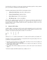
Figure 4-1 - Error Sources in Resistance Measurements
Figure 4-1 illustrates how the 4-wire principle is used to eliminate lead, wire and contact resistances as
potential error sources. The internal current source inherently overcomes all series resistance (within
compliance voltage limits) and delivers a precise constant current. The internal high-impedance DVM senses
the voltage drop across the load. There is negligible contact and lead resistance error created by the voltage
measurement because the high input impedance of the DVM limits current flow in the voltage leads.
4-3.
Setting Voltage and Test Current
The Full Scale Voltage is selected via three interlocking push-buttons. Three LED's directly above the push-
buttons indicate which range has been selected. The Test Current is selected via a six-position rotary switch.
Six LED's mounted to the left of the switch determine the resistance range that will be displayed as indicated
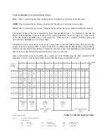
by the front panel matrix. The resistance range is found on the matrix at the intersection of the Voltage Range
and Current Range LED's.
The test current may be turned off and on via the front panel Test Current switch, by a command from the
IEEE interface board, or by a remote switch using Option "RS" as described in Section 3. An LED positioned
directly above the Test Current switch indicates the status of the current source.
4-4.
Charging Inductor Mode
The Charging Inductor mode LED indicates when the standard current source compliance voltage of 7 volts is
exceeded. In this situation the 4300B provides a booster shot in excess of 20V to reduce the settling time
when a large inductive load is being measured. The display readings should be ignored when this LED is
illuminated.


