- 9 -
g
SYMBOLS
Carefully observe the symbols in fig. B and memorise their respective
meanings. Correct interpretation of the symbols allows safer use of
the machine.
1 Machine model
2 Technical data
3 Batch number (the first 2 figures of the batch number indicate the
year of manufacture)
V Volt
Hz Hertz
~
alternating current
Direct current
W Watt
mm millimetres
m metres
s seconds
kg kilograms
no
no load speed
min-1 revolutions per minute
dB decibel
We thank you for having preferred us in choosing this electric tool,
hereinafter called ‘multi-tool’, ‘electric tool’ or ‘apparatus’.
!
!
WARNING! The multi-tool with the supplied accessories is
suitable for dry sanding of wood, iron, plastic and similar materials
using the respective abrasive sheets.
The appliance is also designed for sawing wood, plastic and similar
materials, and for scraping bonded carpets, residual mastic, old
varnishes and similar applications.
Other accessories may extend the range of use, refer to the relevant
documentation. The use of hazardous materials and in environments
with fire risk is prohibited.
The multi-tool is intended for hobby and non-professional use.
This instruction contains the information and all that is deemed ne-
cessary for the good use, knowledge and normal maintenance of the
tool. They do not report information on the processing techniques of
the various materials; the user will find more information on books
and specific publications or by taking part in specialization courses.
COMPONENTS
Refer to fig. A and following, attached to these instructions.
1. Battery compartment
2. Main handle
3. additional handle
4. Tool location
5. Tool mounting flange
6. Tool release lever
7. Start / stop switch
8. Electronic speed regulator
9. Scraper
10. Backing pad
11. Abrasive paper
12. Lama
13. LED light
INSTALLATION
WARNING! The manufacturer is not liable for any direct and/or
indirect damage caused by incorrect connections.
WARNING! Before carrying out the following operations, make
sure that the battery is disconnected from the tool.
TRANSPORT
Always use the packaging or case (when provided) when transporting
the tool; this will protect it from impact, dust and humidity which can
compromise normal operation.
During transport, remove the abrasive disc, brush, etc. from the
machine.
HANDLING
Firmly grasp the handgrip (Fig.A, 2) without using the switch; keep
the tool well away from your body and after use place it down gently
without hitting.
SWITCHING ON
When choosing where to use the power tool, the following should be
considered:
- that the place is not damp and is protected from the weather.
- that there is a large working area free from obstacles.
- that there is good lighting.
- that it is used close to the main switch with residual current device.
- that the power supply system is earthed and conforms to the stan-
dards (only if the power tool is class I, which is equipped with an
earth cable plug).
- that the room temperature is between 10° and 35°C.
- that the environment is not in a flammable/explosive atmosphere.
Take out the machine and components and visually check that they
are perfectly intact; then proceed to thoroughly clean them in order to
remove any protective oils from metal surfaces.
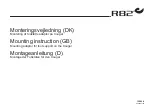
ASSEMBLY OF TOOLS
Tools with open connection
: follow the pictograms shown in
Fig.C
.
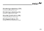
Tools with closed connection
: follow the pictograms shown in
Fig.D
.
!
!
Warning: Wear gloves to protect your hands.
!
!
Attention: the pins / teeth must enter the tool housing.
- Check that the tool is well fixed.
Fastening of abrasive sheets
- The abrasive sheet is applied by exerting a slight pressure on the
velcro, replacing it by pulling it.
SIDE HANDGRIP ASSEMBLY (Fig.A, 3)
The lateral handgrip can be assembled on any side on which there is
a threaded hole; it is usually secured on the left in order to grab hold
with the left hand, but it can be assembled in the position of your
preference (e.g. for left-handed people). Insert the handgrip into the
threaded hole of the device and secure by screwing tightly.
CHARGING THE BATTERY (follow the instructions attached to the
battery charger)
!
!
WARNING! Before using the apparatus it is necessary to fully
charge the battery.
!
!
WARNING! Recharge only with a battery charger designed for
this type of tool. An inappropriate battery charger can cause a fire
hazard when used with other battery units.
To keep the battery in good working order, do not discharge it
completely.
Fully charge the battery:
- After each use.
- At least every 4 months, even if not used.
- If while working you notice a clear drop in the performance of the tool.
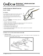
INSERTING AND REMOVING THE BATTERY (Fig. E)
- Insert the battery through the guides in the battery compartment (1).
- Take out the battery from its housing in the tool by operating the
release device (8).