C.T.M. HS-2850, User Manual
The C.T.M. HS-2850 is a robust mobility scooter designed for reliability and comfort. Ensure optimum usage by downloading the free User Manual directly from manualshive.com. This detailed manual provides all the necessary operating and maintenance instructions to enhance your experience. Get your free manual today and enhance your product usage!
Share
Download


Reviews:
No comments
Related manuals for HS-2850
Giraffe
Brand: Jenx Pages: 44

S2
Brand: panthera Pages: 9
S2
Brand: panthera Pages: 9
S3
Brand: panthera Pages: 2
X3
Brand: Garaventa Lift Pages: 7
400
Brand: Accora Pages: 3
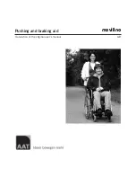
Movilino
Brand: AAT Pages: 36
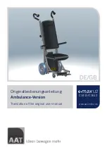
c-max U2
Brand: AAT Pages: 64
S-max
Brand: AAT Pages: 44

RS
Brand: Zippie Pages: 60
MS-04
Brand: Jenx Pages: 24

triplex
Brand: B+B Pages: 71
Jewel
Brand: Magic Mobility Pages: 12
Evo
Brand: Pandhora Pages: 72
Cougar
Brand: R82 Pages: 4
Cougar
Brand: R82 Pages: 5
Rickshaw
Brand: Cando Pages: 2
Combi
Brand: Handicare Pages: 32


