background image

Compa II series 

Maintenance and cleaning


07.15 Operating 

manual 

87


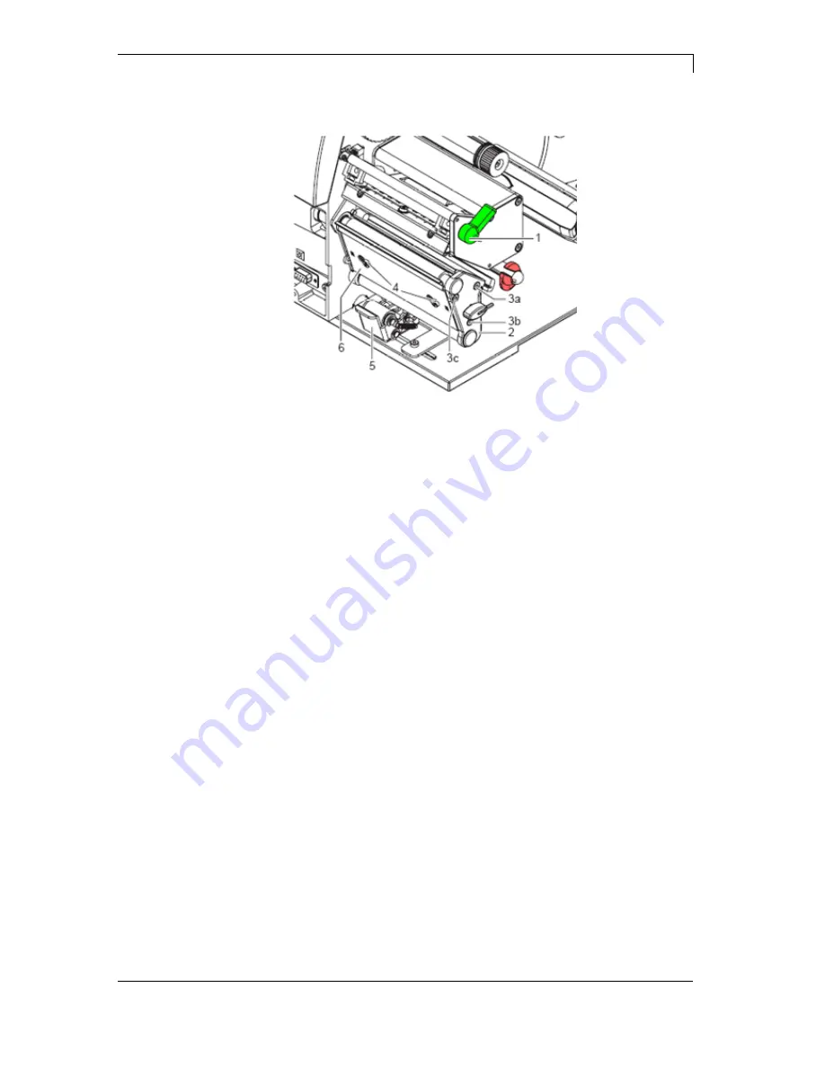
9.6  Replacing the print roller and rewind assist roller 


Figure 24 


1.  Turn lever (1) counter clockwise to lift up the printhead. 
2.  Lift the pinch roller (5) off the rewind assist roller. 
3.  Remove labels and transfer ribbon from the label printer. 
4.  Loosen screws (4) on plate (6) with hexagonal wrench by several 

turns and remove plate (6). 

5.  Unscrew screws (3a, b, c) of the side plate (2) with hexagonal 

wrench. 

6.  Remove side plate (2). 


Removing the 
side plate 

Summary of Contents for Compa II Series

Page 1: ...COMPA II Operating Manual...

Page 2: ...between manual and device can occur Please check www carl valentin de for the latest update Trademarks All named brands or trademarks are registered brands or registered trademarks of their respective...

Page 3: ...9 5 2 Removing wound roll 35 5 3 Loading fanfold labels 36 5 4 Loading transfer ribbon 37 5 5 Setting feed path of transfer ribbon 38 5 6 Removing and or installing rewind guide plate 39 6 Function me...

Page 4: ...r roller 82 9 3 Cleaning the printhead 82 9 4 Cleaning the label photocell 83 9 5 Replacing the printhead 85 9 6 Replacing the print roller and rewind assist roller 87 10 Error correction 89 11 Additi...

Page 5: ...and or an USB memory stick The label printer automatically recognizes by which interface it is controlled Time saving printer update is possible by interface Thanks to the large number of options the...

Page 6: ...lled can therefore be returned to Carl Valentin GmbH This way you can be sure your old equipment will be disposed of correctly Carl Valentin GmbH thereby fulfils all obligations regarding timely dispo...

Page 7: ...2 01 Adjusting screw for transfer ribbon regulating shaft 02 Transfer ribbon for regulating shaft 03 Printhead lock 04 Printhead 05 Label material guiding 06 Return pulley 07 Printer roller 08 Label p...

Page 8: ...erial interface RS 232 6 Ethernet 10 100 interface 7 USB host for USB keyboard and USB memory stick 8 Parallel interface for Centronics 9 External input output option Printer rear 6 1 LED orange 6 1 L...

Page 9: ...pon agreement with the manufacturer Unauthorized interference with electronic modules or their software can cause malfunctions Other unauthorized work or modifications to the direct print module can e...

Page 10: ...ading media and chapter 9 Maintenance and cleaning These indications are also valid for someone else s equipment supplied by us Only use original spare and exchange parts Please contact the manufactur...

Page 11: ...0 of nominal value Allowable tolerance of power line frequency 2 2 of nominal value Allowable distortion factor of power line voltage 5 In case your net is infected e g by using thyristor controlled m...

Page 12: ...es to the corner shell It is not allowed to guide lines parallel to power lines If a parallel guiding cannot be avoided a distance of at least 0 5 m has to be observed Temperature of lines between 15...

Page 13: ...and test printing Herewith you avoid faulty results reports and evaluation Only specially trained staff is allowed to operate the printers Control the correct handling of our products and repeat trai...

Page 14: ......

Page 15: ...r Internal unwinder 200 mm Internal rewinder 145 mm option Core diameter 40 mm 75 mm option Winding outside or inside Label sensor transmission and reflexion from below Transfer ribbon Ink outside or...

Page 16: ...ze in width and height 0 8 5 6 zoom 2 9 orientation 0 90 180 270 Vector fonts TrueType fonts size in width and height 1 99 mm variable zoom orientation 360 in steps of 90 Font attributes depending on...

Page 17: ...uter diameter 180 mm Thermal and thermal transfer version USB host for connection of an external USB keyboard and an USB memory stick Ethernet interface CVPL protocol and ZPL II protocol Label photoce...

Page 18: ...ed The ports are provided by means of a D Sub bushing 26pin HD at the rear panel of the printer system and are galvanically isolated from protective earth PE by means of an optocoupler semi conductor...

Page 19: ...ommon reference potential of all control inputs COM VDC for Inputs is usually connected with the terminal of the control voltage and the control inputs are switched to active By means of the option 2n...

Page 20: ...nector Manufacturer W P Products Reference number 110 26 2 1 20 Output Voltages connected with GND PE 24 V 1 A Fuse Polyswitch 30 V 1 A 5 V 1 A Fuse Polyswitch 30 V 1 A Port 1 15 Input Tension 5 VDC 2...

Page 21: ...Compa II series Technical data 07 15 Operating manual 21 Device connection to a machine with S7 300 SPS Figure 6 Device connection to a operating panel Figure 7 Example 1 Example 2...

Page 22: ...s internal voltages 5 VDC EXT or 24 VDC EXT is used an external fuse e g 0 5 AF should be additionally installed to protect the printer electronics In the event of an inductive load an antiparallel co...

Page 23: ...by the Search for new hardware by means of the hardware wizard Windows 2000 XP Vista 7 Printers can be recognized during the starting procedure of Windows or by the Search for new hardware by means of...

Page 24: ......

Page 25: ...printers with option cutter only Documentation Printer driver on CD ROM Labelstar Office LITE on CD ROM NOTICE Retain original packaging for subsequent transport 4 1 Setting up the label printer CAUTI...

Page 26: ...connection socket Insert plug of power cable into a grounded electrical outlet NOTICE Insufficient or missing grounding can cause faults during operation Ensure that all computers and connection cable...

Page 27: ...see chapter 5 Loading media page 29 Go to menu Label layout select menu item Measure label and start measuring see chapter 6 4 Label layout page 47 Press key to finish measuring NOTICE To enable corr...

Page 28: ......

Page 29: ...to be positioned above the outer label edge Figure 9 1 Loosen knurled screw 1 turn guiding 2 upwards and move it to the outside as far as possible 2 Insert label roll on the roll holder so you can se...

Page 30: ...perpendicular to the direction of paper flow for adaptation to the label medium The sensor unit 1 of the label sensor is visible from the front through the print unit and is marked with an indentatio...

Page 31: ...round the deviating shaft 4 to the internal rewinder 2 2 Hold rewinder 2 firmly and turn knob 3 clockwise until it stops 3 Push label strip under a bracket 1 of the rewinder and turn knob 3 counter cl...

Page 32: ...the housing wall 5 Turn guiding 2 upwards to the roll holder 3 and push it towards the label roll to decelerate it when unwinding 6 Tighten knurled screw 1 1 Turn lever 5 anticlockwise to lift up the...

Page 33: ...ner to the rewinder 2 around the peel off edge 6 and deviating shaft 5 4 Hold rewinder 2 firmly and turn knob 3 in clockwise direction as far as it will go 5 Push backing paper under a bracket 1 of th...

Page 34: ...on prevent premature wearing of the print roller and printhead Figure 14 1 Turn lever 2 clockwise to lock the printhead 2 Position the right plunger 1 onto the centre of the used label material 3 Duri...

Page 35: ...nd roll Figure 15 1 Turn lever 5 anticlockwise to lift up printhead 2 Cut label strip and wind it fully around the rewinder 2 3 Hold rewinder 2 firmly and turn knob 3 clockwise The rewinder spindle re...

Page 36: ...4 behind the label printer Ensure that the labels on the strip are visible from above 4 Guide label strip to print unit via the roll retainer 3 5 Push guiding 2 against the label strip swivel it upwa...

Page 37: ...IPA must be observed In the case of skin or eye contact immediately wash off the fluid thoroughly with running water If the irritation persists consult a doctor Ensure good ventilation 1 Turn lever 4...

Page 38: ...erials can lead to printer malfunctions and the guarantee can expire 5 5 Setting feed path of transfer ribbon Transfer ribbon wrinkling can lead to print image errors Transfer ribbon deflection can be...

Page 39: ...peel off plate or a tear off plate may need to be installed NOTICE For printer versions with a locking system on the rewind roller the locking system on the rewind roller must be removed for operation...

Page 40: ......

Page 41: ...enu one menu item back Change to the quantity number of pieces menu Press keys and to select the number of labels that should be printed Change to the menu of the CF card In main menu feed of one labe...

Page 42: ...inting Measure label Label type Material selection Photocell Scan position Label error length Synchronisation Flip label Rotate label Alignment Label Layout Field handling Codepage External parameters...

Page 43: ...enser I O option IO profile Operating modes Debounce Start signal delay Operating modes Application mode Support delay On Support delay Off Pressure control Vacuum control Blow time Waiting position R...

Page 44: ...M1 Baud Parity Data bits Stop bit Interface Start sign Stop sign Data memory Port test Protocol Printhead resolution Drive mapping Emulation Set date time Summertime Start of summertime format Start o...

Page 45: ...unter Heater resistance Printhead temperature Motor ramp Print examples Input Output Online Offline Transfer ribbon prior warning Zero point adjustment Print length Service Functions Load layout Chang...

Page 46: ...rs at the printer display Strong sensibility The printer reacts immediately to the end of the transfer ribbon Weak sensibility The printer reacts at approx 1 3 more slowly to the end of the transfer r...

Page 47: ...automatically after termination of measuring The determined values are displayed and saved Press key to arrive the next menu item Generally adhesive labels are set Press key to select continuous labe...

Page 48: ...d It is recommended to use labels with the same width as the printhead Otherwise this can cause problems in positioning Press key to arrive the next menu item According to standard the label is printe...

Page 49: ...ther fields are kept Press key to arrive the next menu item Indication of the font used in the printer The following possibilities are available Codepage 1252 West European former ANSI Codepage 437 En...

Page 50: ...ain after print end Additionally a query appears demanding the number of copies that should be print Auto no quant The question referring the customized variable appears again after print end However...

Page 51: ...sible and therefore the backfeed of label is no necessary and time can be saved The adjustable deceleration time is only for mode backfeed automatic of importance see chapter 11 3 page 102 Press key t...

Page 52: ...or multiple labels are advanced 6 6 Network Switch on the label printer and the display shows the main menu Press key to access the function menu Press key as long as you arrive the Network menu Pres...

Page 53: ...top bits between bytes Value range 1 or 2 stop bits Press key to arrive the next menu item SOH Start of data transfer block Hex format 01 ETB End of data transfer block Hex formal 17 Two different sta...

Page 54: ...PL II emulation the printhead resolution of the emulated printer must be set e g 11 8 Dot mm 300 dpi NOTICE If the printhead resolution of the Zebra printer differs from that of the Valentin printer t...

Page 55: ...This entry refers to the previously selected format Example summertime is automatically adjusted at last Sunday in March 03 Press key to arrive the next menu item By means of this function you can de...

Page 56: ...and can be changed Press key to arrive the next menu item This function enables definition of photocell levels In case of problems while positioning or measuring of label levels for label photocell c...

Page 57: ...material Bar codes Printout of all available bar code types Fonts Printout of all available font types Press key to arrive the next menu item Indication of signal level which indicates the signal a pr...

Page 58: ...t be continued at the same position on the label the difference can be corrected NOTICE The value for zero point adjustment is set ex works After replacing the printhead only service personnel are all...

Page 59: ...nter In the upper line of display the cutter mode can be selected In the line below the cutter offset approx 20 mm can be set Press key to change to the next operating mode Off The print order is proc...

Page 60: ...A cut is released by an external I O External can only be selected if the label printer is equipped with option external I O Nach jedem gedruckten Etikett wird ein Schnitt ausgel st Press key to arri...

Page 61: ...sideration I O static continuous For description of this operating mode see I O static Continuous means that it is printed as long as new data is transferred via interface The set dispenser offset is...

Page 62: ...uenced by interface The printer internal function is deactivated The modification of the signal level is only taken into consideration for the operating modes I O static I O dynamic I O static continu...

Page 63: ...t ready set If the start signal was released already before so this is ignored Press key to arrive the next parameter Selection of the available configurations Std_Label factory setting or StdFileSetL...

Page 64: ...file to load 2 Input 6 Number of the file to load 3 Input 7 Number of the file to load 4 Input 8 Number of the file to load 5 Input 9 Error Output 10 Print order active Output 11 Dispenser photocell L...

Page 65: ...e Print Apply The print of a label is released by an external start signal At the same time the vacuum on the pad as well as the supporting air from the blow tube are switched on If the label is print...

Page 66: ...el on the surface of pad Value range 0 2500 ms Step size 10 ms Default 500 ms Press key to arrive the next parameter With activated compressed air control with help from a compressed air sensor it is...

Page 67: ...sition down In cyclic mode the printed label is transported to the labelling position at the end of a cycle So the next cycle begin with blowing up the label Press key to arrive the next parameter Thi...

Page 68: ...he corresponding output for setting and or resetting the output signals can be selected With keys and the corresponding output can be set or reset Input signals I1 Pre dispense key 1 key pressed 0 key...

Page 69: ...e display shows the main menu Press key to access the function menu Press key as long as you arrive the WLAN menu Press key to select the menu The menu item WLAN can only be selected if a WLAN card wa...

Page 70: ......

Page 71: ...m it is recommend to copy the most important data by means of a commercial Card Reader 8 2 Display Structure Load layout A STANDARD File_name1 prn File_name2 prn File_name3 prn File_name4 prn 1 Curren...

Page 72: ...previous menu Function Load layout Change to the File Explorer File Explorer Change to the context menu Select a file directory if a multiple selection is possible Main menu Access to the memory menu...

Page 73: ...of CF card is effected at PC and thus the STANDARD directory was not created automatically The user directory is the root directory in which the user saves usually the most frequently used files layo...

Page 74: ...d as user directory 8 5 Load Layout Loads a layout within a defined user directory The function allows quick access to the desired layout as only layout files are displayed and directories hidden Pres...

Page 75: ...press key to access to the File Explorer Following functions are available Change drive and or directory Load file Save layout and or configuration Delete file s Format CF card Copy file s Selection...

Page 76: ...ey to load the selected file If the selected file is a layout then the number of copies to print can be entered immediately Saves the currently loaded layout under the selected name Press key to acces...

Page 77: ...ned Deletes one or more files and or directories irrevocably With the deletion of a directory both the contained files and the subdirectories are deleted Press key to access to the memory menu Press k...

Page 78: ...ory card NOTICE USB sticks cannot be formatted at the printer Press key to access to the memory menu Press key to call the File Explorer Select the drive which is to format with the navigation keys Pr...

Page 79: ...ress key to call the File Explorer Press keys and to select the file Press key to mark the files which are to be copied The marked entries are listed with Repeat this procedure until all desired files...

Page 80: ...prn is selected loaded In the first step the printer executes the firmware update After the necessary restart automatically the file data prn is loaded In this way the remaining components were update...

Page 81: ...label photocell see section 9 4 page 83 When exchanging the label roll Replacing printhead see section 9 5 page 85 In case of errors in printout Replacing print roller and rewind roller see section 9...

Page 82: ...cleaner and a soft cloth 4 If the roller appears damaged replace it see section 9 6 Replacing the print roller and rewind assist roller on page 87 9 3 Cleaning the printhead Printing can cause accumul...

Page 83: ...head 2 Remove labels and transfer ribbon from the label printer 3 Remove hexagonal wrench 5 from its retainer 4 Press the latch 3 and slowly pull label photocell outwards via the tab 4 Ensure that the...

Page 84: ...r until it stops and unplug the cable 2 from the plug on the rear end of the label photocell 1 5 Press the latch 6 and slowly pull label photocell outward via the tab 5 That way the distance plate 3 i...

Page 85: ...2 1 Head plate 2 Plug connection 3 Plug connection 4 Screw 5 Printing line 6 Pins 7 Printhead CAUTION The printhead can be damaged by static electricity discharges and impacts Set up printer on a grou...

Page 86: ...printhead mounting bracket 9 if necessary 7 Loosen both plug connections 2 3 on the printhead and set printhead down on a clean soft surface 1 Attach plug connections 2 3 2 Position printhead in print...

Page 87: ...ter clockwise to lift up the printhead 2 Lift the pinch roller 5 off the rewind assist roller 3 Remove labels and transfer ribbon from the label printer 4 Loosen screws 4 on plate 6 with hexagonal wre...

Page 88: ...Slide print roller 7 and rewind assist roller 8 onto their respective shafts and turn slightly until the hexagon of the shaft engages in the hexagon socket of the print roller 4 Set side plate 2 Figu...

Page 89: ...available Check font 7 Vector font Selected font is not available Check font 8 Measuring label While measuring no label was found Set label length is too large Check label length and if labels are in...

Page 90: ...ntered res received check digit is wrong Calculate check digit anew Check code data 21 Invalid SC number Selected SC factor is invalid for EAN res UPC Check SC factor 22 Invalid number of digits Enter...

Page 91: ...printhead and start print order anew 36 BCD invalid format BCD error Invalid format for the calculation of Euro variable Check entered format 37 BCD overflow BCD error Invalid format for the calculati...

Page 92: ...ger required files 54 File directory exists The selected file directory already exists Check name select a different name 55 File too large During copying procedure not enough memory space onto target...

Page 93: ...e printhead 71 Invalid page As page number either 0 or a number 9 is selected Select a number between 1 and 9 72 Page selection A page which is not available is selected Check the defined pages 73 Pag...

Page 94: ...use an offset 88 RFID verify Error while checking programmed data Faulty RFID label Check RFID definitions 89 RFID timeout Error at programming the RFID label Label positioning Faulty label 90 RFID d...

Page 95: ...wn is missing option APL 100 Check input signals compressed air supply 102 Vacuum plate empty Sensor does not recognise a label at vacuum plate option APL 100 Check input signals compressed air supply...

Page 96: ...ics for cross traverse 116 Print position The print position is not correct Check TOP and RIGHT final position switch for correct function and position Check pneumatics for function 117 XML parameter...

Page 97: ...settings of the photocell are not correct Check label photocell settings Settings of label size and gap size are not correct Check correct loading of label material No label found at the rear printhe...

Page 98: ......

Page 99: ...he largest x coordinate i e it has the largest distance to the printhead Press key to access the function menu Press key as long as you arrive the menu Label layout Press key to confirm the selection...

Page 100: ...n at the start of a print order the data of the current label is saved to the corresponding directory of the CF card However the following conditions have to be fulfilled CF card inserted in drive A E...

Page 101: ...ized entry was active during switching off the label printer the window for the first customized variable is displayed As in the intended file only the start values of the counter are saved they are r...

Page 102: ...e entry of mask and the function menu By this means the user indeed can print labels but the printer set up and the masks of the labels can t be changed To receive a most flexible password protection...

Page 103: ...igit number possible values 0000 9999 has to be entered Now the modifications can be made The user can define the password in the first line four digit number Press key to continue Press keys and to a...

Page 104: ...essary Tear off edge After printing the last label of a print order it is driven into the tear off offset and the label res labels can be taken away When starting a new print order first it is backtra...

Page 105: ...en it is not driven into tear off offset but the following label is directly printed Dispenser After printing the label during driving into dispensing offset the following label is pre printed if this...

Page 106: ...he top res the receiver at the bottom i e the infra red light is sent from the top The label detection is same as for the transmission photocell normal from the top However it is printed differently a...

Page 107: ...Save configuration 77 Save layout 76 Connecting printer 26 Control inputs and outputs 19 D Dispenser plate removing installing 39 Drawings 6 7 8 E Environmentally friendly disposal 6 Error messages Er...

Page 108: ...Maintenance schedule 81 Print roller cleaning 82 Print roller replacing 87 88 Printhead cleaning 82 Printhead replacing 85 86 Rewind assist roller replacing 87 88 Tools 81 Material loading 29 O Opera...

Page 109: ...edge removing installing 39 Transfer ribbon loading 37 38 U USB Stick Change directory 75 Copying 79 Delete file 77 Display structure 71 Filter 80 Firmware update 80 Load file 76 Load layout 74 Navig...

Page 110: ...Carl Valentin GmbH Neckarstra e 78 86 u 94 78056 Villingen Schwenningen Phone 49 0 7720 9712 0 Fax 49 0 7720 9712 9901 info carl valentin de www carl valentin de...

Reviews: