background image

42 


4.6 Angled 

Radiation 

Shield 


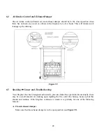
When passing through a combustible wall with the chimney at a 30

 or 45

 angle (30

 or 45

 in 

Canada and 30

 only in the USA), an angled radiation shield provided by the chimney 

manufacturer must be installed. Only one is required. Follow the chimney manufacturer’s 
installation instructions. 
 
In cold climate locations, it is recommended that you use the insulated wall radiation shield since 
it will maintain the home’s thermal barrier. 


Figure 36 

4.7 Chimney 

Support 

Installation 

4.7.1 Universal Roof Support 

 
This support has three possible uses: 

1.  It must be used on a roof to support the chimney. 

2.  It may be used on a floor, ceiling or roof above an offset to support the chimney above the 

offset. 

3.  It may be used on a floor, ceiling or roof as a supplementary support. 
 
For roof support installation, refer to the instructions provided with the support by the chimney 
manufacturer.  Many manufacturers will provide the maximum height of chimney that can be 
supported by the support. Make sure you respect those parameters.


Summary of Contents for FP-7-LM ANTOINETTE

Page 1: ...l Inc 250 rue de Copenhague St Augustin de Desmoures Quebec Canada G3A 2H3 Tel 418 878 3040 Fax 418 878 3001 www valcourtinc com READ AND KEEP THIS MANUAL FOR REFERENCE This manual is available for fr...

Page 2: ...f this fireplace and the chimney that it is connected to Consult your municipal building or fire department about installation requirements in your area We recommend that you also inform your home ins...

Page 3: ...nts 13 3 6 Framing Facing Mantel and Combustible Shelf 14 3 6 1 Framing 14 3 6 2 Facing 21 3 6 3 Combustible Shelf 24 3 7 Fresh Air Kit 27 3 7 1 Fresh Air kit Installation 27 3 8 Faceplate Installatio...

Page 4: ...losed exhaust damper 48 B Negative pressure in the house 49 C Wet wood 49 D Dirty or blocked chimney 49 E Chimney not long enough 49 F Poor chimney draft 49 7 0 MAINTAINING YOUR FP7 LM ANTOINETTE WOOD...

Page 5: ...EN THERE IS A FIRE BURNING IN THE FIREPLACE CAUTION NEVER USE GRATE OR ELEVATE FIRE BUILD WOOD FIRE DIRECTLY ON HEARTH CAUTION DO NOT USE A FIREPLACE INSERT AND OTHER PRODUCTS NOT SPECIFIED FOR USE WI...

Page 6: ...e to be followed in the absence of local code requirements In the USA the NFPA 211 Standard for Chimneys Fireplaces Vents and Solid Fuel Burning Appliances and the ANSI NFPA 70 National Electrical Cod...

Page 7: ...urers of decorative wood burning fireplaces to encourage manufacturers to produce clean wood burning appliances that reduce air pollution Under the U S EPA Low Mass Fireplace Voluntary Program cleaner...

Page 8: ...PEN POSITION 3 1 Installation of a Gas Log Set You can install a decorative gas appliance or a vented gas log set in the hearth To do this install an automatic shut off valve Comply with the Standard...

Page 9: ...nces to combustible materials You will find the spacers heat shield and screws in the firebox see Figure 2 and 3 Figure 2 Spacers 2X Figure 3 Heat shield 1X 3 2 1 Spacers 1 Fold by hand the 2 spacers...

Page 10: ...ll the fire baffles 1 To install the first fire baffle D hold it in your hands with the narrowest part towards the back of the unit Figure 3 3 A 2 Move the piece up to the top bracket at the back of t...

Page 11: ...11 Figure 3 3 A Figure 3 3 B Figure 3 3 C Figure 3 3 D Figure 3 3 E Figure 3 3 F Figure 3 3 G D E...

Page 12: ...r roof rafters B Usually no additional floor support is needed for the fireplace The adequacy of the floor can be checked by first estimating the weight of the fireplace system Weights are given in th...

Page 13: ...end at least 16 40 cm in front and at least 8 20 cm on each side of the door opening see Figures 8 and 10 The joint between the hearth extension and the fireplace hearth needs to be made of non combus...

Page 14: ...d the following illustrations Figures 12 to 18 A Frame the fireplace using 2 3 5 cm x 8 cm or heavier lumber WARNING COMBUSTIBLE FRAMING MATERIAL CANNOT BE USED IN THE SPACE DIRECTLY ABOVE THE FIREPLA...

Page 15: ...ers between the vertical studs only as follows Place 2 x 3 or 2 x 4 headers only along the upper part of the front side and back faces Do not put wood or any combustible material within the area above...

Page 16: ...16 Figure 13 Figure 14...

Page 17: ...17 Figure 15...

Page 18: ...18 Figure 16...

Page 19: ...19 Figure 17 Insulated chase construction...

Page 20: ...20 Figure 18 Spacers must be installed...

Page 21: ...surround must be non combustible and have the minimal dimensions as shown on Figure 12 2 Non combustible materials such as brick stone or ceramic tile may project in front of and onto the fireplace de...

Page 22: ...22 Facing With the Narrow Overlap Figure 19...

Page 23: ...23 Facing With the Masonry Trim Figure 20...

Page 24: ...lace Different shelf dimensions are listed in the table below and in Figure 22 in order to facilitate installation The depth of the shelf can be 6 or less but can t be installed at less than 46 127 cm...

Page 25: ...25 SHELF POSITIONING SHELF DIMENSION SHELF POSITION 6 152 mm 46 1168 mm 8 203 mm 48 1219 mm 10 254 mm 50 1270 mm 12 305 mm 52 1321 mm Figure 22...

Page 26: ...26 Figure 23...

Page 27: ...installed more than 10 ft 3 m above the base of the fireplace C The fresh air must come from outside the house The air intake must not draw air from the attic from the basement or from a garage D The...

Page 28: ...28 Figure 24 Figure 25...

Page 29: ...the air inlets Carefully push the insulation and plastic cover back over the pipe Secure the plastic in place using aluminum tape 3 8 Faceplate Installation Sold Separately 3 8 1 Narrow Overlap WARNIN...

Page 30: ...NING THE PLATING OF THE MASONRY TRIM SHOULD NEVER COME IN CONTACT WITH MASONRY PRODUCT SUCH AS MORTAR ACID OR ANY OTHER PRODUCTS CONTAINING ABRASIVES DAMAGES AND DISCOLOURATION CAUSED BY THESE PRODUCT...

Page 31: ...trim is installed you may proceed with the installation of the non combustible wall all types of cement board See section 3 6 2 5 Install the non combustible material on top of the cement board and ag...

Page 32: ...ut 6 the screen door 7 Tighten the 2 bolts Figure 29 4 0 Venting System Chimney and Chimney Connector 4 1 General The venting system is the engine that drives your wood heating system Even the best fi...

Page 33: ...he building code enforced locally The chimney must have either a clay liner or a suitably listed stainless steel liner If the masonry chimney has a square or rectangular liner that is larger in cross...

Page 34: ...SEE IMAGE BELLOW IT SHALL BE CUT ABOVE THE LIFTING HOOKS WELDED TO THE INSIDE OF THE FLUE OUTLET SO THAT THE ANCHOR PLATE RESTS PERFECTLY ON TOP OF THE FIREPLACE CAUTION IF THE FLUE OUTLET IS CUT ONLY...

Page 35: ...mney systems described in table 1 3 A chimney venting a fireplace shall not vent any other appliance 4 The minimum chimney system height for a straight installation is 15 ft 4 6 m including the height...

Page 36: ...lems 10 Cut and frame square holes in all floors ceilings and roof that the chimney will go through to provide a 2 50 mm minimum clearance between the chimney and any combustible materials Do not fill...

Page 37: ...he chase enclosure and at least 2 ft 61 cm higher than any wall roof or building within 10 ft 3 1 m of it See Figure 31a and 31b to determine the configuration that applies to your roof flat or sloped...

Page 38: ...chimney lengths making sure to lock each length in place according to the chimney manufacturer s instructions In many cases it is recommended to secure connections with three 3 12 mm metal screws 4 E...

Page 39: ...39 EXAMPLE OF TYPICAL CHIMNEY INSTALLATION Figure 33...

Page 40: ...required offset Lock the chimney lengths together according to the chimney manufacturer s instructions In many cases it is recommended to use three 3 12 mm metal screws If the offset length is made of...

Page 41: ...41 Figure 34 Figure 35...

Page 42: ...ll maintain the home s thermal barrier Figure 36 4 7 Chimney Support Installation 4 7 1 Universal Roof Support This support has three possible uses 1 It must be used on a roof to support the chimney 2...

Page 43: ...re you respect those parameters 4 8 Chimney Chase and Multiple Terminations For the purpose of this manual a chimney chase is considered a part of the chimney system rather than part of a building The...

Page 44: ...he liner to the insulated chimney Verify availability and installation instructions for this connector with the chimney manufacturer Follow these steps 1 Position the fireplace in its location Tempora...

Page 45: ...iting a chimney fire if the chimney is creosoted CAUTION DO NOT OVER FIRE THIS HEATER OVER FIRING CAN RESULT IN A SAFETY HAZARD AND CAN PERMANENTLY DAMAGE THE FIREPLACE AND CHIMNEY 5 1 The Use of Manu...

Page 46: ...tart a fire place several crumpled up balls of newspaper in the firebox behind the andiron Place small dry pieces of kindling on top of the paper criss crossing the kindling so that there are air spac...

Page 47: ...has been consumed or partially consumed and you have obtained a good bed of embers you should reload the unit In order to do so proceed by opening the glass door or the screen door for you to have en...

Page 48: ...e chimney Figure 39 6 5 Smoking Causes and Troubleshooting Your fireplace has been designed and tested to provide smoke free operation Occasionally there may be a small amount of smoking upon lighting...

Page 49: ...rior chimney start with an offset etc F Poor chimney draft With no fire there should be sufficient draft to exhaust cigarette smoke introduced at the bottom of the throat Chimneys installed against an...

Page 50: ...From this you will learn how often it will be necessary to clean your chimney B Have your chimney cleaned by a qualified chimney sweeper If you wish to clean it yourself we recommend using a stiff pl...

Page 51: ...he possible danger 3 If you require assistance alert your fire department 4 If possible use a dry chemical fire extinguisher baking soda or sand to control the fire Do not use water as it may cause a...

Page 52: ...t Do not use the fireplace with a broken or missing refractory panel Here are the steps to replace the refractory panels of your FP 7 LM Antoinette fireplace 1 Remove the Andirons VA7070 by unscrewing...

Page 53: ...2 1 Figure 42 2 Figure 42 3 Figure 42 4 Figure 42 5 WARNING DO NOT USE MATERIALS OTHER THAN THOSE LISTED IN THE REPLACEMENT PARTS SECTION DURING INSTALLATION AS THEY MAY BE SAFETY HAZARDS AND A FIRE C...

Page 54: ...BY SLAMMING IT AGAINST THE FIREPLACE WARNING DO NOT OPERATE THE FIREPLACE WITH A CRACKED OR BROKEN GLASS WARNING DO NOT USE MATERIALS OTHER THAN THOSE LISTED IN THE REPLACEMENT PARTS SECTION DURING IN...

Page 55: ...aner which is available in your area Regular household glass cleaners will not clean creosote and they usually contain ammonia that may stain the glass permanently WARNING ONLY WASH THE GLASS WHEN IT...

Page 56: ...lesale price of the replacement part All parts and labour costs covered by this warranty are limited according to the table below The manufacturer at its discretion may decide to repair or replace any...

Reviews: