110
Screen shot
Setting
Description
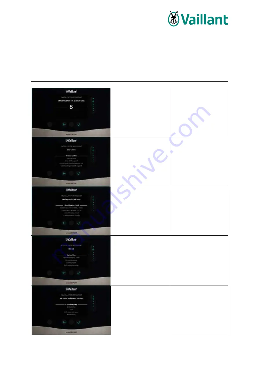
8, 10 or 16 for heat pumps
Diagram number for heat pumps
is 8 for a direct system,
10 for indirect i.e. hex exchanger
module
16 for a cascade system using
VR32B eBUS cards
(master/slave cascade system will
use 8/10 normally – consult the
relevant drawing schematic)
No Solar system or
solar system DHW support
Only applicable if the solar sys-
tem is Vaillant and has been wired
into the VR70/71, not applicable if
a VRS 570 has been used or none
Vaillant solar system
(only shown if VR70/71 installed)
Select the number of heating
circuits
Heating circuits and zones.
If a VR70 is installed, then the
number and type of circuits need
to be selected.
If VR71 is installed, then you only
select the number of zones and
the display is simplified to that of
the adjacent example
(only shown if VR70/71 installed)
FM3 or FM5 MO selection
FM3=VR70 terminal R3
FM5=VR71 terminal R4
This is to select what the mul-
tifunction output terminal is
operating from the VR70/71
(only shown if VR70/71 installed)
HP control module MO2 function
MA2 on VWZ AI MB2
This is to select what is con-
nected to MA2 in the heat pump
interface VWZ AI MB2
Summary of Contents for UK aroTHERM plus
Page 119: ...119...


