7 Start-up
24
Installation and maintenance instructions ecoTEC plus 0020261188_00
2.
Alternatives 2 / 2
‒
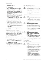
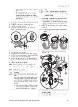
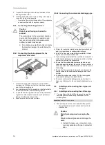
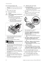
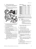
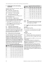
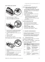
Measuring the gas pres-
sure at the gas connection:
▶
Undo the test nipple screw
(C)
at the gas connec-
tion.
▶
Connect a digital manometer or U-tube manometer
(D)
.
3.
Open the gas stopcock.
4.
Open the hydraulic circuit's valves.
5.
Start up the product with the check programme
P.01
.
6.
Measure the gas flow pressure in comparison with the
atmospheric pressure.
Gas connection pressure/gas flow pressure
difference for G20
Permitted gas flow
pressure that is
measured at point
(D)
Permitted gas flow
pressure that is
measured at point
(B)
VC 406/5-5
(E-DE)
1.70 … 2.50 kPa
(17.00
… 25.00 mbar)
1.60 … 2.40 kPa
(16.00
… 24.00 mbar)
VC 476/5-5
(E-DE)
1.70 … 2.50 kPa
(17.00
… 25.00 mbar)
1.60 … 2.40 kPa
(16.00
… 24.00 mbar)
VC 636/5-5
(E-DE)
1.70 … 2.50 kPa
(17.00
… 25.00 mbar)
1.55 … 2.35 kPa
(15.50
… 23.50 mbar)
Gas connection pressure/gas flow pressure
difference for G25
Permitted gas flow
pressure that is
measured at point
(D)
Permitted gas flow
pressure that is
measured at point
(B)
VC 406/5-5
(E-DE)
2.00 … 3.00 kPa
(20.00
… 30.00 mbar)
1.85 … 2.83 kPa
(18.50
… 28.30 mbar)
VC 406/5-5
(LL-DE)
2.00 … 3.00 kPa
(20.00
… 30.00 mbar)
1.85 … 2.83 kPa
(18.50
… 28.30 mbar)
VC 476/5-5
(E-DE)
2.00 … 3.00 kPa
(20.00
… 30.00 mbar)
1.85 … 2.83 kPa
(18.50
… 28.30 mbar)
VC 476/5-5
(LL-DE)
2.00 … 3.00 kPa
(20.00
… 30.00 mbar)
1.85 … 2.83 kPa
(18.50
… 28.30 mbar)
VC 636/5-5
(E-DE)
2.00 … 3.00 kPa
(20.00
… 30.00 mbar)
1.85 … 2.85 kPa
(18.50
… 28.50 mbar)
VC 636/5-5
(LL-DE)
2.00 … 3.00 kPa
(20.00
… 30.00 mbar)
1.85 … 2.85 kPa
(18.50
… 28.50 mbar)
Gas connection pressure/gas flow pressure
difference for G31
Permitted gas flow
pressure that is
measured at point
(D)
Permitted gas flow
pressure that is
measured at point
(B)
VC 406/5-5
(E-DE)
2.50 … 4.50 kPa
(25.00
… 45.00 mbar)
2.45 … 4.45 kPa
(24.50
… 44.50 mbar)
VC 406/5-5
(LL-DE)
2.50 … 4.50 kPa
(25.00
… 45.00 mbar)
2.45 … 4.45 kPa
(24.50
… 44.50 mbar)
VC 476/5-5
(E-DE)
2.50 … 4.50 kPa
(25.00
… 45.00 mbar)
2.45 … 4.45 kPa
(24.50
… 44.50 mbar)
VC 476/5-5
(LL-DE)
2.50 … 4.50 kPa
(25.00
… 45.00 mbar)
2.45 … 4.45 kPa
(24.50
… 44.50 mbar)
VC 636/5-5
(E-DE)
2.50 … 4.50 kPa
(25.00
… 45.00 mbar)
2.35 … 4.35 kPa
(23.50
… 43.50 mbar)
VC 636/5-5
(LL-DE)
2.50 … 4.50 kPa
(25.00
… 45.00 mbar)
2.35 … 4.35 kPa
(23.50
… 43.50 mbar)
7.
Decommission the product.
8.
Close the gas stopcock.
9.
Remove the manometer.
10. Tighten the test nipple screw
(A)
or
(C)
.
11. Open the gas stopcock.
12. Check the test nipple for gas tightness.
Conditions
: Gas flow pressure not in the permissible range
▶
If you are unable to eliminate the fault, contact the gas
supply company.
▶
Close the gas stopcock.
7.8.3
Checking the CO
₂
content and, if
necessary, adjusting it (air ratio setting)
1.
Ensure that the heating circuit valves are open.
2.
Start up the product with the check programme
P.01
.
3.
Wait at least five minutes until the product reaches its
operating temperature.
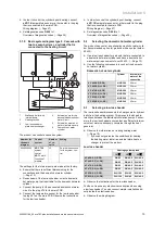
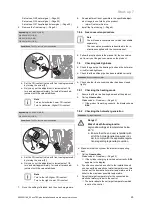
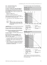
1
4.
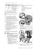
Measure the CO
₂
content at the flue gas analysis point
(1)
.
5.
Compare the measured value with the corresponding
value in the table.

