background image

7 Start-up

20

Installation and maintenance instructions ecoTEC plus 0020261188_00

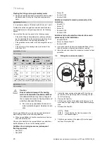
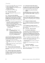
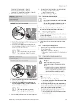
Treating the filling and supplementary water

Observe all applicable national regulations and technical
standards when treating the filling and supplementary
water.

Applicability:

Germany

In particular, observe VDI directive 2035, sheets 1 and 2.

Provided the national regulations and technical standards
do not stipulate more stringent requirements, the following
applies:

You must treat the heating water in the following cases:

If the entire filling and supplementary water quantity dur-
ing the operating life of the system exceeds three times
the nominal volume of the heating installation, or

If the guideline values listed in the following table are not
met, or

If the pH value of the heating water is less than 8.2 or
more than 10.0.

Applicability:

Germany

OR Luxemburg

Total
heating
output

Water hardness at specific system volume

1)

20 l/kW

> 20 l/kW

50 l/kW

> 50 l/kW

kW

°dH

mol/m

³

°dH

mol/m

³

°dH

mol/m

³

< 50

< 16.8 < 3

11.2

2

0.11

0.02

> 50
to

200

11.2

2

8.4

1.5

0.11

0.02

> 200
to

600

8.4

1.5

0.11

0.02

0.11

0.02

> 600

0.11

0.02

0.11

0.02

0.11

0.02

1) Nominal capacity in litres/heating output; in the case of multi-
boiler systems, the smallest single heating output is to be used.

Applicability:

Germany

OR Luxemburg

Caution.
Risk of material damage if the heating
water is treated with unsuitable additives.

Unsuitable additives may cause changes in
the components, noises in heating mode and
possibly subsequent damage.

Do not use any unsuitable frost and cor-
rosion protection agents, biocides or seal-
ants.

No incompatibility with our products has been detected to
date with proper use of the following additives.

When using additives, follow the manufacturer's instruc-
tions without exception.

We accept no liability for the compatibility of any additive or
its effectiveness in the rest of the heating system.

Additives for cleaning measures (subsequent
flushing required)

Adey MC3+

Adey MC5

Fernox F3

Sentinel X 300

Sentinel X 400

Additives intended to remain permanently in the
installation

Adey MC1+

Fernox F1

Fernox F2

Sentinel X 100

Sentinel X 200

Additives for frost protection intended to remain
permanently in the installation

Adey MC ZERO

Fernox Antifreeze Alphi 11

Sentinel X 500

If you have used the above-mentioned additives, inform
the end user about the measures that are required.

Inform the end user about the measures required for frost
protection.

7.2

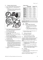
Filling the condensate siphon

1

2

3

C

B

A

1.

Unclip the lower section of the siphon

(1)

from the up-

per section of the siphon

(2)

without removing the pro-

duct's front casing.

2.

Remove the float

(3)

.

3.

Fill the lower section of the siphon with water up to 10
mm below the upper edge of the condensate discharge
pipe.

4.

Re-insert the float

(3)

.

Note

Check whether the float is present in the
condensate siphon.

5.

Clip the lower section of the siphon

(1)

into the upper

section of the siphon

(2)

.

Summary of Contents for ecoTEC plus VC 406/5-5

Page 1: ...and maintenance instructions ecoTEC plus VC 406 5 5 VC 636 5 5 DE LU Publisher manufacturer Vaillant GmbH Berghauser Str 40 D 42859 Remscheid Tel 49 21 91 18 0 Fax 49 21 91 18 2810 info vaillant de ww...

Page 2: ...Telefon 04621 30 60 89 0 Mail info unidomo com ffnungszeiten Mo Fr 8 00 17 00 Uhr a member of DAIKIN group Individuelle Beratung Komplettpakete Kostenloser Versand ber 15 Jahre Erfahrung Hochwertige...

Page 3: ...plementary water 19 7 2 Filling the condensate siphon 20 7 3 Filling the heating installation 21 7 4 Starting up the product 21 7 5 Running the installation assistants 21 7 6 Preventing low water pres...

Page 4: ...ance of accompanying operating installation and servicing instructions for the product and any other system compon ents installing and fitting the product in accord ance with the product and system ap...

Page 5: ...paint 1 3 6 Risk of death due to lack of safety devices The schematic drawings included in this doc ument do not show all safety devices re quired for correct installation Install the necessary safet...

Page 6: ...lue system Ensure that the supply of combustion air is always free of fluorine chlorine sulphur dust etc Ensure that no chemical substances are stored at the installation site If you are installing th...

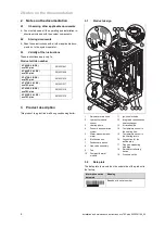
Page 7: ...0010021518 VC 636 5 5 LL DE ecoTEC plus 0010021519 3 Product description This product is a gas fired wall hung condensing boiler 3 1 Product design 6 1 3 2 8 9 10 11 12 13 14 15 16 17 18 19 7 5 4 1 R...

Page 8: ...output range in heating mode Pnc Nominal heat output range in heating mode condensing technology Tmax Maximum flow temperature NOx NOx class for the product Code DSN Specific product code Read the in...

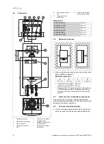
Page 9: ...5 mm VC 476 5 5 LL DE 405 mm VC 636 5 5 E DE 473 mm VC 636 5 5 LL DE 473 mm 4 4 Minimum clearances C C A B D When using the accessories observe the minimum clear ances installation clearances Minimum...

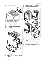
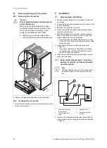
Page 10: ...g 4 8 1 Removing the front casing A B B C D 1 Undo the screw A 2 Push in both retaining clips B so that the front casing is released 3 Pull the front casing forwards at the bottom edge C 4 Lift the fr...

Page 11: ...icable national and international laws standards and directives With older installations in particular install a magnetic filter at the heating circuit return in order to protect the product against d...

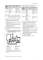
Page 12: ...ternal pump for the decoupled heating circuit 5 Heating circuit 6 Domestic hot water cylinder In order to use this basic diagram type ensure that the minimum flow volumes are guaranteed for the operat...

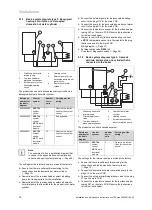
Page 13: ...tic hot water cylinder Connect the external pump for the decoupled heating circuit to the plug X16 for the main PCB Connect the pump for the decoupled domestic hot water circuit to the plug X13 for th...

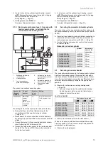
Page 14: ...diagram Page 47 Set diagnostics code D 026 to 1 Overview of diagnostics codes Page 39 5 2 Selecting the domestic hot water cylinder The product can control an optional domestic hot water cylin der re...

Page 15: ...gas tank is not purged properly this may result in ignition problems Ensure that the liquid gas tank has been purged properly before installing the product If required contact the filler or the liquid...

Page 16: ...or leak tightness 5 5 3 Hydraulic connection Caution Risk of material damage caused by corro sion Due to non diffusion tight plastic pipes in the heating installation air gets into the heating water A...

Page 17: ...ge pipe 1 2 Follow the instructions listed here and observe the legal and local regulations on condensate discharge Use PVC or any other material that is suitable for drain ing the non neutralised con...

Page 18: ...is being used by other products Observe the applicable international national and local regulations for flue systems in particular for installations in living rooms Inform the end user how to correct...

Page 19: ...s if necessary 10 Plug the plug into the slot provided on the PCB in ac cordance with the wiring diagram in the appendix 5 7 3 Establishing the power supply 1 Observe all valid regulations The applica...

Page 20: ...r Status codes in the display provide information on the pro duct s current operating mode Status codes Overview Page 42 6 4 Calling up appliance config and diagnostics menu To recheck and reset the m...

Page 21: ...itable additives Unsuitable additives may cause changes in the components noises in heating mode and possibly subsequent damage Do not use any unsuitable frost and cor rosion protection agents biocide...

Page 22: ...DE 0 15 0 25 MPa 1 50 2 50 bar 0 40 MPa 4 00 bar VC 406 5 5 LL DE 0 15 0 25 MPa 1 50 2 50 bar 0 40 MPa 4 00 bar VC 476 5 5 E DE 0 15 0 25 MPa 1 50 2 50 bar 0 40 MPa 4 00 bar VC 476 5 5 LL DE 0 15 0 25...

Page 23: ...the required target heating temperature 7 5 5 Setting the target hot water temperature This setting is only possible if a domestic hot water cylin der optional is installed in the system This means th...

Page 24: ...le must be completely carried out once so that the burner can ignite 7 8 Check and gas setting 7 8 1 Checking the factory setting Caution An incorrect gas type setting may cause malfunctions or a redu...

Page 25: ...bar VC 636 5 5 E DE 2 00 3 00 kPa 20 00 30 00 mbar 1 85 2 85 kPa 18 50 28 50 mbar VC 636 5 5 LL DE 2 00 3 00 kPa 20 00 30 00 mbar 1 85 2 85 kPa 18 50 28 50 mbar Gas connection pressure gas flow pressu...

Page 26: ...ly The conversion procedure is described in the in structions supplied with the conversion set Follow the instructions in the manual for the conversion set to carry out the gas conversion on the produ...

Page 27: ...set burner anti cycling time can be found in the following table TFlow target Set maximum burner anti cycling time min 1 5 10 15 20 25 30 30 2 0 4 0 8 5 12 5 16 5 20 5 25 0 35 2 0 4 0 7 5 11 0 15 0 18...

Page 28: ...he automatic pump mode D 014 0 and defining a target value for the available pressure e g D 122 200 mbar it is possible to adjust the balancing valves for the various radiators To guarantee that the p...

Page 29: ...sures taken to ensure the combustion air supply and flue system Point out in particular that the end user must not make any changes however minor 10 Troubleshooting You can find an overview of the fau...

Page 30: ...contact the contact address provided on the reverse of these instructions If you require spare parts for maintenance or repair work use only the spare parts that are permitted for the product 10 9 2 P...

Page 31: ...embly if it is defective 1 2 4 3 13 Remove the retainer 2 for the gas valve assembly To do this undo the three screws 1 14 Undo the fixing screws 3 for the Venturi 15 Remove the Venturi 4 16 Replace t...

Page 32: ...ove the rainwater drain hose 6 from the heat ex changer 7 Remove the plug 5 1 3 2 4 8 Remove the screws 1 and 3 9 Remove the retainer for the heat exchanger 2 and 4 10 Pull the heat exchanger downward...

Page 33: ...stall the new temperature sensor 3 When reinstalling note the colour of the conductors Blue conductor Heating return Red conductor Heating flow 10 9 8 Replacing the pump 3 1 2 4 1 Pull out the plug 5...

Page 34: ...The electronics are now set to the product type model and the parameters for all diagnostics codes are set to the default settings The display automatically restarts with the installa tion assistant...

Page 35: ...old water pipe 7 Drain the product when you are carrying out work on hydraulic components Page 37 8 Ensure that water does not drip on live components e g the electronics box 9 Use only new seals 11 3...

Page 36: ...ex changer using water or if required vinegar up to a maximum acid content of 5 Allow the vinegar to act on the heat exchanger for 20 minutes 3 Use a plastic brush or sufficiently strong jet of water...

Page 37: ...s 2 3 Carefully remove the electrode 3 from the combustion chamber 4 Ensure that the electrode ends are undamaged 5 Clean and check the gap between the electrodes Clearance for the ignition electrodes...

Page 38: ...he pipe and insert the clip 11 3 10 Checking the pre charge pressure of the external expansion vessel 1 Depressurise the heating installation 2 Measure the pre charge pressure of the expansion ves sel...

Page 39: ...ance work 12 Decommissioning 12 1 Permanently decommissioning Decommission the product Disconnect the product from the power grid Close the gas stopcock Close the heating stopcocks Drain the product P...

Page 40: ...07 Target value for the domestic hot water cylinder temperature in C 15 C frost protection 40 C up to D 020 max 70 C Not ad justable D 009 Heating flow temperature target value from external eBUS cont...

Page 41: ...External solenoid valve 6 External fault message 7 Solar pump not active 8 eBUS remote control not active 9 Anti legionella pump not activated 2 D 029 Heating flow heating circuit or cylin der chargin...

Page 42: ...rt ups in heat ing mode Number of burner start ups x 100 Not ad justable D 083 Number of burner starts in domestic hot water mode Number of burner start ups x 100 Not ad justable D 084 Maintenance ind...

Page 43: ...S 23 DHW mode Ignition S 24 DHW mode Burner on S 25 DHW mode Pump fan overrun S 26 DHW mode Fan overrun S 27 DHW mode Pump overrun S 28 Domestic hot water burner anti cycling time Special cases S 30...

Page 44: ...ure sensor short circuit NTC sensor defective Replace the NTC sensor Short circuit in the cable har ness Check the cable harness F 20 Safety shutdown Safety cut out Flow NTC defective Check the flow N...

Page 45: ...ter The gas pressure monitor has been triggered Check the gas flow pressure Air in the gas supply Check the gas air ratio Gas flow pressure too low Check the gas flow pressure The thermal isolator dev...

Page 46: ...flow NTC F 72 Flow and or return temper ature sensor fault Flow NTC defective Replace the flow NTC Return NTC defective Replace the return NTC F 73 Water pressure sensor signal in the wrong range too...

Page 47: ...ctive Replace the flue non return flap No feedback from the condens ate pump or the feedback is in correct Check that the condensate pump is working correctly F 83 Fault Flow and or return temperature...

Page 48: ...F RF AF FB X51 X51 L N L N L N L N 24V RT BUS Burner off FUS X20 X2 X16 X13 X11 X18 X40 X51 X30 X22 X41 X24 X1 X100 X35 X90 X12 X31 24V 230V X11 L N X18 L N X1 L N 1 2 3 4 L N X13 X51 eBUS Burner off...

Page 49: ...th the system control op tional 9 Temperature sensor for the low loss header op tional 10 Plug for the domestic hot water cylinder s temperat ure sensor optional 11 Plug for the domestic hot water cyl...

Page 50: ...Appendix 0020261188_00 ecoTEC plus Installation and maintenance instructions 49 E Basic installation diagram E 1 0020253233...

Page 51: ...Appendix 50 Installation and maintenance instructions ecoTEC plus 0020261188_00 E 2 0020259030...

Page 52: ...x2 xn F Inspection and maintenance work Overview The table below lists the manufacturer requirements with respect to minimum inspection and maintenance intervals If na tional regulations and directiv...

Page 53: ...asing removed 9 0 1 0 vol 9 0 1 0 vol 9 0 1 0 vol Set for Wobbe index W 14 1 kW h m 14 1 kW h m 14 1 kW h m O after 5 minutes in full load mode with front cas ing closed 4 5 1 8 vol 4 5 1 8 vol 4 5 1...

Page 54: ...e default setting D 71 75 75 Range for the heating flow temperature control 30 80 30 80 Maximum permissible pressure PMS 0 4 MPa 4 0 bar 0 4 MPa 4 0 bar Nominal water flow T 20 K 2 500 l h 2 500 l h A...

Page 55: ...DE VC 636 5 5 LL DE Effective output range P at 50 30 C 12 0 62 1 kW 12 0 62 1 kW Effective output range P at 80 60 C 11 1 58 4 kW 11 1 58 4 kW Maximum heat input heating Q max 60 0 kW 60 0 kW Minimum...

Page 56: ...r CE number PIN CE 0063CS3428 CE 0063CS3428 Smoke mass flow in heating mode at P min 3 9 g s 3 9 g s Smoke mass flow in heating mode at P max 20 3 g s 20 3 g s Released system types C13x C33x C43x C53...

Page 57: ...efficiency at 60 40 C 102 8 102 8 Nominal efficiency in partial load mode 30 at 40 30 C 109 4 109 4 NOx class 6 6 Product dimensions width 440 mm 440 mm Product dimensions depth 473 mm 473 mm Product...

Page 58: ...Appendix 0020261188_00 ecoTEC plus Installation and maintenance instructions 57 VC 636 5 5 E DE VC 636 5 5 LL DE IP rating IPX4D IPX4D Permissible connected voltage 195 253 V 195 253 V...

Page 59: ...s for the parameters 29 Fault code 28 Fault memory 28 Filling the heating installation 21 Flow temperature maximum 28 Flue gas route 4 Front casing closed 5 Frost 5 Function menu 33 G Gas connection 1...

Page 60: ...nts 33 Serial number 7 Service message 28 Service partner 28 Setting the CO content 24 Setting the pump curve 27 Setting the pump output 27 Side section installing 10 Side section removing 10 Spare pa...

Page 61: ...Telefon 04621 30 60 89 0 Mail info unidomo com ffnungszeiten Mo Fr 8 00 17 00 Uhr a member of DAIKIN group Individuelle Beratung Komplettpakete Kostenloser Versand ber 15 Jahre Erfahrung Hochwertige...

Page 62: ...8 0 Telefax 021 91 18 2810 Auftragsannahme Vaillant Kundendienst 021 91 5767901 info vaillant de www vaillant de These instructions or parts thereof are protected by copyright and may be reproduced or...

Reviews: