


WallVIEW PRO Z700 Installation and User Guide 341-674 Rev. B
Page 4 of 12
Step 4:
Attach the Cat. 5 cables for Power, Video and Control to the EZIM and feed the excess Cat. 5 cabling into
the wall opening or wall box.
Step 5:
Place the camera onto the camera mount and using the ¼”-20 screw to secure the camera to the mount.
Step 6:
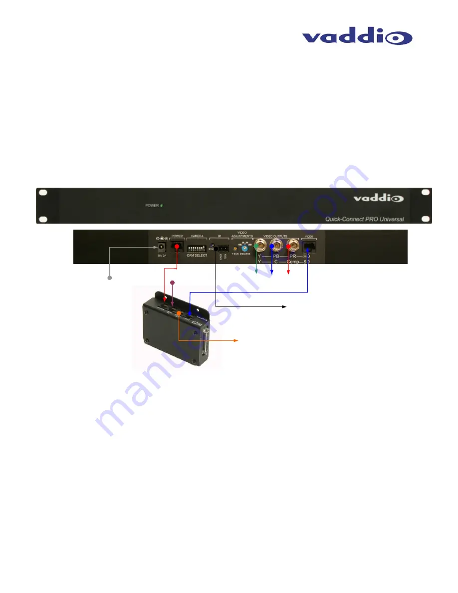
The Quick-Connect PRO is a 1-RU rack mount interface that breaks out the signals from the Cat. 5 cables
back to the standard connectors. The basic system connectivity is illustrated in Figure 6.
Step 6 (continued):
Attach the Cat. 5 cables for Power, Video and Control to the Quick-Connect PRO interface. Connect the HD
video output BNC connectors. Connect the PowerRite 36 VDC power supply to the Quick-Connect PRO
power input. Please check all Cat. 5 cables for continuity in advance of final connection.
Note: Plugging the POWER Cat. 5 Cable into the wrong RJ-45 may cause damage to the camera system and void the warranty.
Step 7:
Connect the Vaddio 36 VDC power supply to an AC outlet. Power will travel down the Power Cat. 5 cable to
the cable shoe, powering the camera. The camera will “Home” to a centered position ready for control
information from the IR remote control or RS-232 camera controller of the integrators’ choice. To insure
proper continuity of control and operation of the cameras, the RS-232 controller (control system or joystick)
should be powered on after the camera.
Figure 6:
Pro Series HSDS
Cable System
Connectivity
RS-232 Out for Daisy Chain Control
Power
Supply IN
HD Component
Video Outputs
Power
Cat. 5
Video
Cat. 5
RS-232 In
Cat. 5
IR Output and Gain Adjust
(forwarded from the IR sensor in
the camera)


