VADDIO WALLVIEW PRO Z700 WITH HSDS Installation And User Manual Download Page 2


WallVIEW PRO Z700 Installation and User Guide 341-674 Rev. B 

                                                                Page 2 of 12 

UNPACKING 

Carefully remove all of the parts from the packaging.  Unpack and identify the following parts: 


  One (1) - Sony BRC-Z700 High Definition PTZ Camera  

  One (1) - Vaddio EZ Interface Module (EZIM) 

  One (1) - Vaddio EZIM to HD camera break out cable 

  One (1) - Vaddio Quick-Connect PRO  with HSDS (1-RU Rack Mountable)  

  One (1) - Vaddio Thin Profile Z700 Wall Mount 

  One (1) - IR Remote Controller 

  One (1) - EZCamera Control Adapter (RJ-45 to DB-9) 

  One (1) - 36V PowerRite™ HD Power Supply with AC Cord Set  

  One (1) - 2-position Phoenix Connector for IR 

 Mounting 

Hardware 

 Documentation 

ƒ

 Vaddio 

Manual 

ƒ

  Sony BRC-Z700 Manual  

 
Optional Accessory: 

Quick-Connect Boxes (2) for SD video (300 ft. limit) Part # - 998-1105-001 


INSTALLATION 

All WallVIEW products are specifically designed for installation on a vertical wall surface with Cat. 5 cable 
connectivity for Power, Video and Control signaling (three cables are required).  Installation is simplified in 
that no custom 8-Pin mini-din cables or expensive S-Video plenum cables are needed and no power outlets 
are required near the camera bracket.  All cabling is routed to the head-end using Cat. 5 cables.


Before Installing 

  Locate the camera mounting location paying close attention to camera viewing angles, lighting conditions, 

possible line of site obstructions, and checking for in-wall obstructions where the camera is to be 
mounted.  Pick a mounting location to optimize the performance of the camera.    

  Pre-wire all cabling as required (see wiring diagram examples).  

  The Thin Profile Wall Mount for the WallVIEW HD1 can be mounted directly to a 3-gang wall box or can 

be mounted to the drywall using four dry wall anchors. 

 
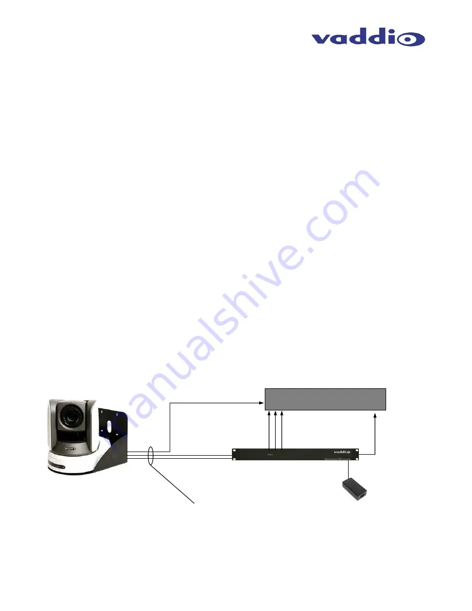
Wiring Diagram Example  
The Basic Idea: 


Figure 2:  

Basic connectivity of the WallVIEW PRO HD-700 System.


The WallVIEW PRO HD-700 uses a Cat. 5 (all 4-pairs) for power to ensure the direct drive motors receive the 
required current to operate properly.  The Video Cat. 5 uses 3-pairs of the Cat. 5 for Video and 1-pair for IR 
forwarding.  The RS-232 Cat. 5 uses 5 conductors for RS-232 with provision for daisy chain controllers.  These Cat. 
5 cables can be run up to 500’ (152.4m).  See Appendix 1 for wiring and pin-out information 

Component Video (Y, Pb, Pr) 

to HD video device 

36 VDC PowerRite 
Power Supply 

IR Output 
(see p. 4) 

WallVIEW Z700 with Camera, Wall 
Mount and EZIM (inside Wall Mount)  

Quick-Connect Pro  

Rack Mount Interface 

Up to 500’ (152.4m) of Cat. 5 
for Power, Video and Control 

Power Cat. 5

Video Cat. 5 

RS-232 Cat. 5 

HD Video Device/Switcher 

Summary of Contents for WALLVIEW PRO Z700 WITH HSDS

Page 1: ...the EZ Interface Module EZIM that fastens to the back of the camera mount Like all Vaddio WallVIEW systems the Thin Profile Wall Mount and mounting hardware is included INTENDED USE Before installing the Vaddio WallVIEW PRO Z700 Camera System please read the entire manual thoroughly All Vaddio camera systems were designed for use indoors Outdoor operation is not recommended has not been tested and...

Page 2: ... Cat 5 cables Before Installing Locate the camera mounting location paying close attention to camera viewing angles lighting conditions possible line of site obstructions and checking for in wall obstructions where the camera is to be mounted Pick a mounting location to optimize the performance of the camera Pre wire all cabling as required see wiring diagram examples The Thin Profile Wall Mount f...

Page 3: ... with wall anchors use four 4 quality wall anchors The mounting holes are slotted and are 90 opposing to provide easy leveling Level the mount and tighten down the mounting screws Step 3 Connect the 25 pin end of the break out cable to the EZIM Next mount the EZIM to the back of the wall mount on the left side using the two tapped screw holes see Figure 6 Connect the 15 pin video cable power conne...

Page 4: ...ick Connect PRO power input Please check all Cat 5 cables for continuity in advance of final connection Note Plugging the POWER Cat 5 Cable into the wrong RJ 45 may cause damage to the camera system and void the warranty Step 7 Connect the Vaddio 36 VDC power supply to an AC outlet Power will travel down the Power Cat 5 cable to the cable shoe powering the camera The camera will Home to a centered...

Page 5: ...ctions are operating from the remote through the camera s IR sensor the IR gain is adjusted properly Connecting an IR Probe If connecting a Xantech IR Probe to the IR output of the Quick Connect Pro the white striped wire on the probe should be connected to the signal SIG terminal and the ground or black wire to GND Attach the probe over the IR window of the codec Make sure the dipswitch is in the...

Page 6: ...tion 100 200 300 400 Compatible Cameras Sony BRC H700 BRC Z700 EVI HD1 BRC 300 EVI D70 EVI D100 also in SD Mode Polycom EagleEye Max Cat 5 Cable Distance Up to 500 152 4m for Video Power and Control Power Supply 36 VDC 2 78 Amp Dimensions 1 RU Rack Mount 1 75 H x 19 W x 6 D EZCamera Interface Module Connectors Four 4 RJ 45 Connectors One DB 25 for Power Video Control IR Cable Assemblies For Sony H...

Page 7: ...2 DSR Sony Daisy chain from DTR 3 Unused 4 Unused 5 Unused 6 Digital GND 7 RXD from TXD of control source 8 TXD to RXD of control source RS 232 OUT Connector Pin Signal 1 DSR Sony Daisy chain from DTR 2 DTR Sony Daisy chain to DSR 3 Unused 4 Unused 5 Unused 6 Digital GND 7 TXD to RXD of control source 8 RXD from TXD of control source Video Connector Pin Signal SD HD 1 IR IR 2 IR GND IR GND 3 Y Y 4...

Page 8: ...Signal 1 GND Out 14 RXD Out 2 TXD Out 15 DTR Out 3 DSR Out 16 GND IN 4 TXD IN 17 RXD IN 5 DTR IN 18 DSR IN 6 IR 19 GND 7 GND 20 CVBS PR 8 GND 21 C PB 9 GND 22 Y Y 10 GND 23 GND 11 GND 24 12V 12 12V 25 12V 13 12V Quick Connect Pin outs Power Connector Pin Signal 1 Power 2 Power 3 Power 4 Power 5 Power 6 Power 7 Power 8 Power Video Connector Pin Signal SD HD 1 IR IR 2 IR GND IR GND 3 Y Y 4 C PB 5 C ...

Page 9: ...ND 5 RXD 6 GND 7 IR OUT 8 Unused RS 232 IN Connector 8 Pin Mini Din Pin Signal 1 DTR 2 DSR 3 TXD 4 GND 5 RXD 6 GND 7 Unused 8 Unused Sony HD Video analog component Pin outs Video Output Connector DB 15HD Pin Signal 1 PR 2 Y 3 PB 4 GND 5 GND 6 GND 7 Unused 8 Unused 9 NC 10 Unused 11 Unused 12 Unused 13 Unused 14 Unused 15 Unused 6 5 8 4 7 3 2 1 6 5 8 4 7 3 2 1 1 6 11 10 5 15 ...

Page 10: ...ipment ICES 003 Compliance This digital apparatus does not exceed the Class A limits for radio noise emissions from digital apparatus set out in the Radio Interference Regulations of the Canadian Department of Communications Le présent appareil numérique n emet pas de bruits radioélectriques dépassant les limites applicables aux appareils numeriques de la classe A préscrites dans le Règlement sur ...

Page 11: ... at support vaddio com or online at www vaddio com Return Material Authorization RMA number Before returning a product for repair or replacement request an RMA from Vaddio s technical support Provide a technician with a return phone number e mail address shipping address and product serial numbers and describe the reason for repairs or returns as well as the date of purchase and proof of purchase ...

Page 12: ... FAX 763 971 4464 www vaddio com 2008 Vaddio All Rights Reserved Reproduction in whole or in part without written permission is prohibited Specifications and pricing subject to change Vaddio WallVIEW Quick Connect EZIM HSDS and PowerRite are registered trademarks of Vaddio All other trademarks are property of their respective owners Document Number 341 674 Rev B ...

Reviews: