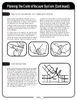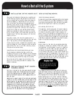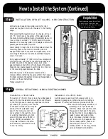
INSTALLATION OF INLET VALVES - NEW CONSTRUCTION
Step 4
Vertical tube lines and low voltage wiring for inlet
valves are roughed in while the house is in the framing
stage.
After selecting the location for an inlet valve, drill a 2
1/4" (57 mm) hole in the center of the plate next to
the stud. Cement sufficient tubing to adapter elbow for
riser or drop to extend 3" (76 mm) beyond the plate.
Assemble the mounting plate to the adapter elbow with
plaster guard tabs facing forward.
Insert tubing through the hole in the plate and nail the
mounting plate to the front of the stud, with the
adapter elbow next to the stud. For appearance, inlet
valve height should be the same as electrical recepta-
cles in the room.
Bring approximately 10" (250 mm) of low voltage wire
through the top oval hole of the mounting plate and
double it back into the adapter elbow. Also allow
approximately 2 feet (.6 m) of wire beyond the plate.
Press the red plaster guard insert firmly into the face
of the mounting plate between the tabs.
After the walls are finished, the inserts will be
removed before installing the valves. After the house is
finished, complete the system following the applicable
portions of these instructions.
Happy vacuuming!
Helpful Hint
Take measurement from floor
to bottom of electrical box.
Add 1-7/8” to get Center Point
of Vac Mounting Plate.
PAGE 8
How to Install the System (Continued)
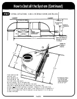
SPECIAL SITUATIONS - NEW & EXISTING HOMES
Step 5
Installation of Inlet Valves
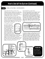
For walls 1/4" (6 mm) thick or less, the rubber gasket
seal on the inlet valve stem should be moved forward
to the front groove to insure a proper seal. A slot is
provided 3/8" (10 mm) from the end
of the stem in order that it may be
sawed off with a standard hack-
saw. If the inlet valve will not
cover a hole in the wall in a new
or existing installation, an inlet
valve trim plate (ivory #5007 or
brown #5008) is available. The
trim plate fits behind the valve
and covers any oversized hole up
to 1/2" (13 mm).
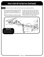
Installation of a Utility Valve
A utility valve is used next to the power unit or in
basements, garages, and other areas where tubing is
exposed. To install, put the screw provided with the
valve into the wall (using an anchor if
necessary) until it protrudes 3/4"
(19 mm). Check 3/4" (19 mm) with
the gauge on the back of the valve.
Connect wiring to low voltage wire-
leads in valve, and push connec-
tions into space provided. Using a
1/8" allen wrench, change valve to
the unlocked position, place over
the screw, and turn to "L" for
locked position. If not snug, remove
valve and adjust screw slightly.

