


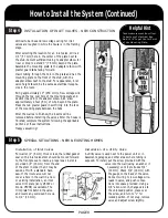

The power unit can be located in the garage, basement,
utility room, or any other area that is dry and remote
enough that living areas will not be affected by the
sound of the electric motor. Preferably install the unit
on an outside wall away from heat-producing units such
as an incinerator, water heater, dryer, etc. (DO NOT
INSTALL POWER UNIT IN ATTIC.) The unit must be
mounted within three feet of an electrical outlet.
Electrical specifications of the power unit should be
checked to avoid overloading the circuit. The unit
should be mounted so that it is out of the way, but still
accessible for emptying.
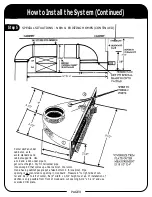
Inlet valves are usually located on inside walls in hall-
ways, near doorways, archways, and near the bottom of
staircases. These locations provide the maximum area
of cleaning coverage with a minimum number of inlet
valves—frequently making it possible to clean three or
four rooms from one valve. The hose must be able to
reach every corner of the house and go around furni-
ture to get there.
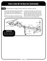
After locating inlet valves, use a 30 foot (9.5 m) length
cord (our standard hose length) or a piece of string to
scale if working with blueprints, to be sure all areas of
the house can be cleaned from selected inlet valve loca-
tions. If an electrical beater brush is to be used now or
in the future, the inlet valve should be located within
five feet of an electrical outlet. Turbine driven beater
brush heads do not require electricity and thus allow
more flexibility when choosing inlet valve locations.
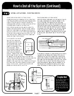
It is preferable to plan on using wall inlet valves; how-
ever, the same inlet valve can be placed in the floor if
tubing cannot be installed in the wall. For basements,
garages, and other areas where tubing is exposed, utili-
ty valves are used. They are installed easily, directly
into our standard tubing.
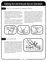
HOW TO DETERMINE LOCATION FOR POWER UNIT
HOW TO DETERMINE LOCATIONS FOR INLET VALVES
Helpful Hint
Vacuums must breath—do not
enclose them! If the unit is to be
located in a closet or utility room,
it must be vented. Louvered doors
fulfill this purpose. A muffler can
be used to minimize noise.
Helpful Hint
When determining locations for
inlet valves, make sure the hose
can reach all areas of the house
including closets, ceiling corners,
and walls. Allow sufficient slack in
the cord to get around furniture.
Helpful Hint
Venting considerations: 1) do not
vent into a wall, a ceiling, or a
concealed space of a building or
structure; 2) avoid venting to
patios and entranceways.
PAGE 2
Planning the Central Vacuum System