


Procedures after repair
24h on-call service phone: +358 (0)40 83 71 150
112
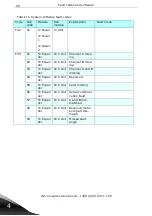
6
12. START-UP AFTER REPAIR
12.1. An external DC power without the motor for FR4 to FR13
Before proceedings to test the unit, check all of the parts, wiring and motor connec-
tions visually, to see that they are correct. There will be dangerously high voltages
present during this test.
12.2. Testing with a DC suppply without the motor connection
Switch off the DC power supply
Connect the power supply's DC+ to the unit's B+ main terminal. Locate an internal
place for the DC+ connection, if the drive does not have a DC+ terminal.
Connect the power supply's DC- to the unit's B- main terminal. Locate an internal
place for the DC- connection, if the drive does not have a DC- terminal.
Set the power supply voltage setting to zero and switch on the DC -power supply.
Increase the voltage slowly to the units nominal DC-voltage (1,35 x Un)
Read the following monitoring and system info values:
The Voltage of the DC link is 1.8 (the same as the supplied DC voltage).
The Unit temperature is V1.9 (estimate, if it corresponds to environmental tempera-
ture)
The Software version (is the same as loaded into the unit)
Ready state or not
Set parameter 2.7.4 (ID 730) to 0 in the standard application. This disables the input
line supervision.
Set the drive to RUN state.
Change the reference frequency from 0 to 50 Hz. Check the output frequency.
Increase the DC voltage to the tripping limit. Check for the over-voltage fault (F2)
indication on the display.
NOTE! DO NOT EXCEED OVERVOLTAGE TRIPPING LIMIT!
Switch off the DC power supply and wait until the DC link has discharged!


