


7
vacon • 70
Technical data
Local contacts: http://drives.danfoss.com/danfoss-drives/local-contacts/
7.3.1
Technical information on control connections
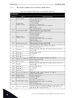
Table 34. Technical information on standard I/O terminals.
Standard I/O
Terminal
Signal
Technical information
1
Reference output
+10V, +3%; Maximum current 10 mA
2
Analogue input,
voltage or current
Analogue input channel 1
0-20 mA (Ri =250
Ω
)
0-10 V (Ri=200k
Ω
)
Resolution 0.1%, accuracy ±1%
Selection V/mA with dip-switches (see chapter 5).
Default 0-10V
Short-circuited protected.
3
Analogue input common
Differential input if not connected to ground;
Allows ±20V differential mode voltage to GND
4
Analogue input,
voltage or current
Analogue input channel 2
0-20 mA (Ri =250
Ω
)
0-10 V (Ri=200k
Ω
)
Resolution 0.1%, accuracy ±1%
Selection V/mA with dip-switches (see chapter 5).
Default 0-20mA
Short-circuited protected.
5
Analogue input common
Differential input if not connected to ground;
Allows 20V differential mode voltage to GND
6
24V aux. voltage
+24V, ±10%, max volt. ripple < 100mVrms; max. 250mA
Short-circuit protected
7
I/O ground
Ground for reference and controls (connected internally to frame earth
through 1M
Ω
)
8
Digital input 1
Positive or negative logic
Ri = min. 5k
Ω
18…30V = "1"
0...5V = “0”
9
Digital input 2
10
Digital input 3
11
Common A for DIN1-DIN6.
Digital inputs can be isolated from ground, see chapter 5.
Default: connected to ground.
12
24V aux. voltage
Same as terminal 6.
13
I/O ground
Ground for reference and controls (connected internally to frame earth
through 1M
Ω
)
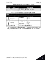
14
Digital input 4
Positive or negative logic
Ri = min. 5k
Ω
18…30V = "1"
0...5V = “0”
15
Digital input 5
16
Digital input 6
17
Common A for DIN1-DIN6.
Digital inputs can be isolated from ground, see chapter 5.
Default: connected to ground.
18
Analogue output,
voltage or current
Analogue output channel 1
0-20 mA (R
L
<500
Ω
)
0-10 V (R
L
>1k
Ω
)
Resolution 0.1%, accuracy ±2%
Selection V/mA with dip-switches (see chapter 5).
Default 0-20mA
Short-circuited protected.
19
Analogue output common
30
24V auxiliary input voltage
Can be used with an external power supply (with a current limiter or fuse
protected) to supply the control unit and fieldbus for backup purposes.
Dimensioning: max. 1000mA/control unit.


