14
Operating instructions VisionLine
14
Mounting the camera
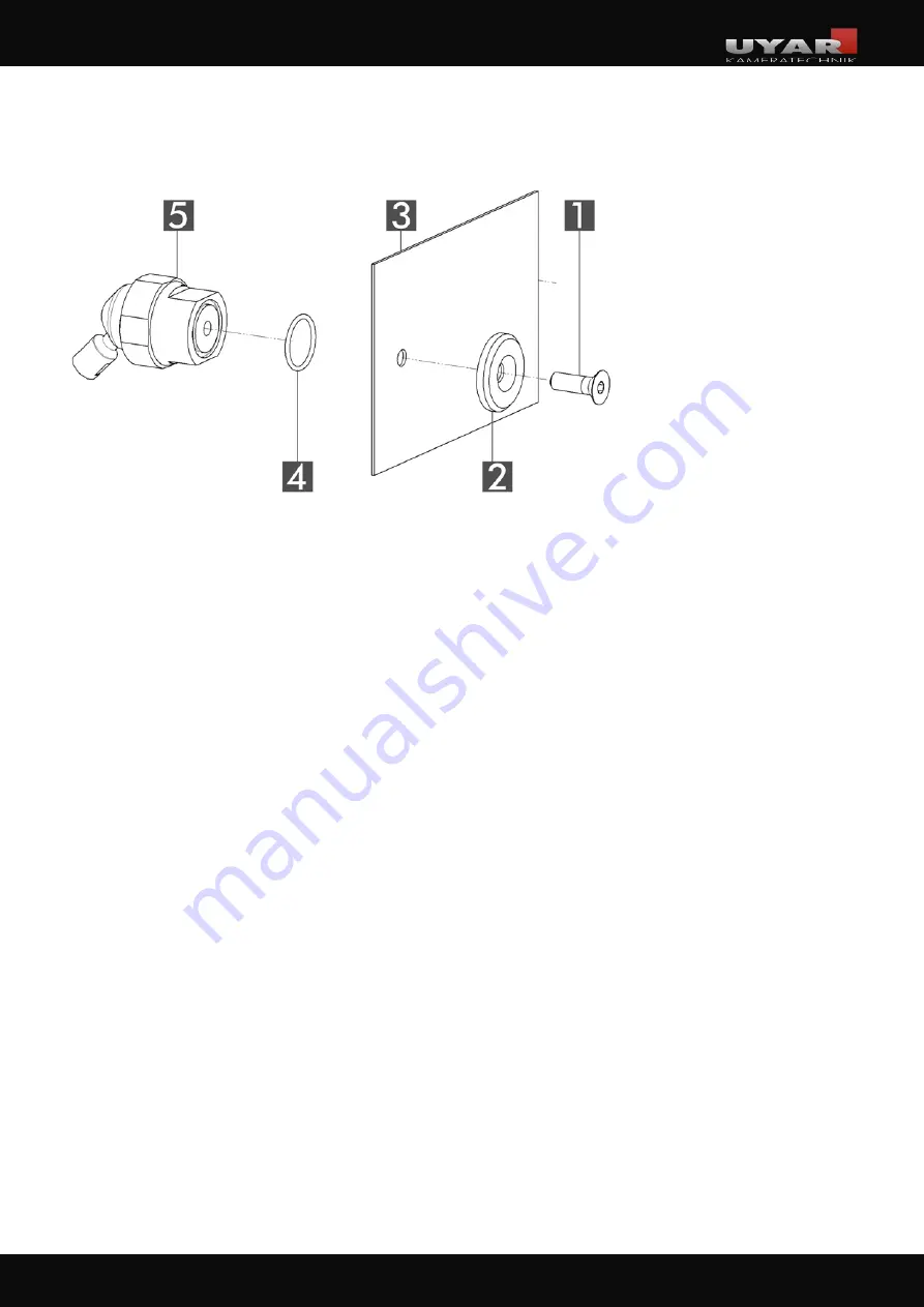
1. counter-sunk screw
2. washer
3. machine wall
4. o-ring
5. external ball joint
If you have not purchased a magnetic holder for your camera system, a Ø8.2mm hole is required at the
position specified in Chapter 3.1. Here the camera is attached to the external ball joint (incl. O-ring)
with washer and countersunk screw (included in delivery) according to the above exploded view.
Depending on the length of your cable-hose- package and the position of the control box, there are
now two different steps:
1. The cable-hose- package is led through the machine wall and connected directly to the control
box.
2. The cable-hose- package is separated (section 3.2.5) and with the wall bushing „double
socket“ (section 3.2.4) led through the machine wall. With this variantion, the control box can be
freely positioned and fastened.


