2.1
95-8600
6
WIrIng ProCEDurE
CautIon
Power must not be applied to the device while
opening the housing or while plugging in or
removing the module.
Disassemble the enclosure by turning the housing
1.
cover counterclockwise. See Figure 5 for an
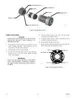
illustration of the xWatch assembly.
Carefully remove the camera module.
2.
Connect the external wiring to the screw connectors
3.
marked A-, B-, C-, and D- on the xWatch terminal
block. See Figure 6.
Important
Do not test any wiring connected to the xWatch
with a meg-ohmmeter. Disconnect wiring at
the camera before checking system wiring for
continuity.
Check all field wiring to be sure that the proper
4.
connections have been made.
Using the index pin as a guide, install the camera
5.
module on the terminal block.
Re-assemble the device housing.
6.
Make the final sighting adjustments and ensure that
7.
the mounting bracket hardware is tight.
QUICK CONNECT PLUG (4)
POWER + (B)
VIDEO + (D)
POWER – (C)
VIDEO – (A)
A2365
INDEX PIN
Figure 6—xWatch Wiring terminal Block
WIRING TERMINAL BLOCK
INDEX PIN
O-RING (2)
HOUSING COVER
CAMERA MODULE
TERMINAL CAP
A2366
QUICK CONNECT PLUG (4)
Figure 5—Exploded view of xWatch

