background image

2.1

95-8600

9

trouBleshootinG

The xWatch camera is not designed to be repaired in the 

field.  If it is determined that the problem is caused by 

an electronic defect, the device must be returned to the 

factory for repair.  

NOTE

It  is  highly  recommended  that  spare  modules 
be  kept  on  hand  for  field  replacement  to  ensure 
continuous protection.

rEPlACIng thE xWAtCh CAMErA MoDulE

CautIon

Power  must  not  be  applied  to  the  device  while 
opening  the  housing  or  while  plugging  in  or 
removing the module.

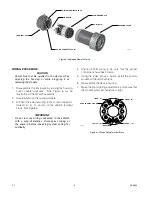
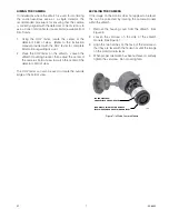
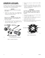
Disassemble  the  enclosure  by  turning  the  housing 

1. 

cover  counterclockwise.    See  Figure  5  for  an 

illustration of the xWatch assembly.
Remove  the  existing  camera  module  from  the 

2. 

xWatch. 
Using the index pin as a guide, install the new xWatch 

3. 

camera module on the terminal block.
Check the housing O-rings and service as required 

4. 

(see Maintenance section of this manual for details).  

Re-assemble the device housing. 
Check camera sighting and ensure that the mounting 

5. 

bracket hardware is tight.
Clean the camera lens if required.

6. 

maintenance

ClEAnIng

The  xWatch  camera  requires  no  periodic  calibration  or 

servicing.  However, the camera lens should be cleaned 

on a regular basis.  

Clean  the  camera  lens  using  a  clean  cloth  or  tissue 

and Det-Tronics window cleaning solution (part number 

001680-001).  If a stronger solution is needed, isopropyl 

alcohol may be used.

o-rIngs

Rubber O-rings are used on the xWatch housing to ensure 

the watertight integrity of the device.  It is imperative that 

these O-rings be properly installed and in good condition.  

Failure to properly maintain these rings can allow water to 

enter the housing and cause premature failure. 

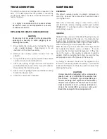
When the housing cover is removed, the O-rings should 

be inspected for breaks, cracks, or dryness.  If cracks 

are visible, the O-ring should be replaced.  If they feel 

dry  to  the  touch,  a  thin  coating  of  lubricant  should  be 

applied.  When re-installing the O-rings, be sure that they 

are properly seated in the groove on the housing.

A  coating  of  lubricant  should  also  be  applied  to  the 

threads on the housing before reassembly.  This will both 

lubricate the threads and help to prevent moisture from 

entering the housing.

CautIon

O-rings  should  be  lubricated  with  a  silicone-free 
grease  (such  as  p/n  005003-001  available  from 
Det-Tronics).    If  catalytic  type  combustible  gas 
sensors are being used anywhere on the premises, 
silicone  based  lubricants  should  never  be  used, 
since  inadvertent  use  of  a  silicone  lubricant  on 
or  near  the  combustible  gas  sensor  will  cause 
irreversible damage to the sensing element.

Summary of Contents for Det-Tronics xWatch X7050

Page 1: ...Instructions 95 8600 xWatch Explosion Proof Camera X7050 2 1 6 09 95 8600 ...

Page 2: ...age 4 Camera Location 5 Camera Mounting 5 Wire Size and Type 5 Wiring Procedure 6 Aiming the Camera 7 Leveling the Camera 7 Converting a C7050 Flame Detector to X7050 xWatch 8 Troubleshooting 9 Replacing the xWatch Camera Module 9 Maintenance 9 Cleaning 9 O Rings 9 Device Repair And Return 10 Ordering Information 10 Accessories 10 Replacement Parts 10 Assistance 10 ...

Page 3: ...ube module in an existing C7050 Flame Detector to provide basic visual information xWatch can be ordered from the factory as a combined unit with any X Series flame detector With this arrangement the camera and detector share the same field of view In the event of a fire or gas alarm the operator can immediatelyviewthemonitoredareatodeterminewhether personnel are present and safe An accurate evalu...

Page 4: ...ing 22 AWG to 16 AWG twisted pair cable of 100 ohm impedance The monitor end must terminate the video cable with 100 ohms Since most monitors have a built in termination resistor of 75 ohms instead of 100 ohms a balun or other matching network video converter must be used A variety of matrix control systems or DVRs can be suitable for viewing or recording the video signal depending on the requirem...

Page 5: ... 2 G Ex d IIC T5 IP66 FM07ATEX0053 Ta 40 C to 75 C IECEx Certificate of Conformity IECEx FMG 07 0019 Ex d IIC T5 IP66 Ta 40 C to 75 C User Interface Conventional off the shelf video switchers and controllers can be used for the interface Housing Material Aluminum or 316 Stainless Steel Shipping Weight Approximate Aluminum 1 2 pounds 0 6 kg Stainless Steel 2 2 pounds 1 0 kg Dimensions See Figures 2...

Page 6: ...roperprecautionsduringinstallation to ensure that moisture will not come in contact with the electrical connections or components of the system The integrity of the system regarding moisture protection must be maintained for proper operation and is the responsibility of the installer If conduit is used drains must be installed at water collection points to automatically drain accumulated moisture ...

Page 7: ...Because composite video frequencies span the range of 25 Hz to 6 MHz most cables will display transmission line characteristics Ensure that the same cable type impedance is used throughout the entire length For example do not mix twisted pair cable and coaxial cable without using a balun for matching In addition the monitor end must be properly terminated Failure to properly implement the video ca...

Page 8: ...ring connected to the xWatch with a meg ohmmeter Disconnect wiring at the camera before checking system wiring for continuity Check all field wiring to be sure that the proper 4 connections have been made Using the index pin as a guide install the camera 5 module on the terminal block Re assemble the device housing 6 Make the final sighting adjustments and ensure that 7 the mounting bracket hardwa...

Page 9: ...a s field of view to match the center of the detector s field of view The COV tester can also be used to locate the outside edge of the field of view Leveling the Camera If the image on the monitor does not appear to be level this can be corrected by rotating the camera module within the xWatch Remove the housing cover from the xWatch See 1 Figure 5 Loosen the setscrew on the side of the xWatch 2 ...

Page 10: ...ector Disconnect the existing wiring at the controller 4 Connect the grounding strap between the new index pin and the terminal mounting screw per the instructions See Figure 9 Important Do not test any wiring connected to the xWatch with a meg ohmmeter Disconnect wiring at the camera before checking system wiring for continuity Check all field wiring to be sure that the proper 5 connections have ...

Page 11: ...s Clean the camera lens using a clean cloth or tissue and Det Tronics window cleaning solution part number 001680 001 If a stronger solution is needed isopropyl alcohol may be used O Rings Rubber O rings are used on the xWatch housing to ensure the watertight integrity of the device It is imperative that these O rings be properly installed and in good condition Failure to properly maintain these r...

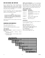
Page 12: ...ng Bracket p n 004404 002 Q1201A Laser Holder Laser is used for sighting the flame detector and xWatch camera The Laser Holder easily attaches to the front of the detector or camera The Laser projects a red laser beam to show the exact center of the field of view Additional laser positions are provided to show the outside edges of the field of view Replacement Parts Part Number Description 009448 ...

Page 13: ...ch Eclipse IR Combustible Gas Detector Eagle Quantum Premier Safety System Eagle Logic Solver Safety System Det Tronics the DET TRONICS logo and xWatch are registered trademarks or trademarks of Detector Electronics Corporation in the United States other countries or both Other company product or service names may be trademarks or service marks of others Copyright Detector Electronics Corporation ...

Reviews: