background image

Order of Assembly  


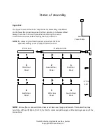
Figure 1-12: 


This figure shows all the main components for assembling a 12x8 floor  
and It shows the proper sequence the floor panels are to be assembled. 
Always finish the first row of panels before starting the second. 
Finish the second row before starting the third and so on.                                  

       Main 


Power Cable 

NOTE:

 It is always a good idea to power up and test the floors


             after assembling  a row to confirm all connections. 


’ tri

 end  


8’ e te sio  tri


  3 


  2 


            1 

                      Third Floor                                     Second Floor                        First Floor 
                           Panel                                                 Panel                                   Panel  


8’ Tri  


        end 


 6 


  5 


   4 

                       Sixth Floor                                        Fifth Floor                        Fourth Floor     
                           Panel                                                 Panel                                   Panel  


NOTE:


All new floors come with brand new never been used plugs and sockets. This means they may 

tend to be stiff and fit tight at first. To fix this it is recommended to apply a little marine grease on all the 
connections.


The ARCH Portable Lighted Dance Floor System 

Copyright USA Dance Floor, LLC


Summary of Contents for ARCH-RGB

Page 1: ...The ARCH RGB Portable Lighted Dance Floor System SETUP and OPERATION INSTRUCTIONS A product of USA Dance Floor LLC Made in the U S A...

Page 2: ...t are open or have no trim These open edges are completed when connected to a jointing panel However these open edges will need trim pieces attached all along two edges of the finished setup See the s...

Page 3: ...ransported or stored up right on its edge Figure 1 2 shows the proper orientation Figure 1 2 Only rest the floor on this side when loading or storing upright on its edge Note Always tuck the short ext...

Page 4: ...t the end of a length See Figure 1 5 Figure 1 3 8 foot powered extension 95 13 16 8 foot powered end piece 89 7 8 4 foot powered end piece 41 7 8 NON POWERED TRIM PIECES Non powered trim pieces have n...

Page 5: ...pieces are used last or at the ends End trim pieces are 8 feet or 4 feet in length Figure 1 5 Powered End Trim Piece This is the shorter 8 foot Powered Extension Trim Piece Powered Extension Trim Piec...

Page 6: ...ill may be used to secure screws only if it has a ratchet drive set at low torque Securing a screw does not mean to tighten it Securing a screw means that the top of the s re s head is le el ith or el...

Page 7: ...ing as shown in figure 1 11 Figure 1 10 Dance Floor Surface Outside Edge inch Figure 1 11 Optional Aluminum Beveled Edging NOTE All new floors come with brand new never been used plugs and sockets Thi...

Page 8: ...idea to power up and test the floors after assembling a row to confirm all connections tri end 8 e te sio tri 3 2 1 Third Floor Second Floor First Floor Panel Panel Panel 8 Tri end 6 5 4 Sixth Floor F...

Page 9: ...this plug in The other is an L shaped corner floor trim piece that connects in the corner of the floor where the Powered and Non Powered trim pieces come together The plugs coming from this piece con...

Page 10: ...e down as shown in Figure 1 16 Figure 1 16 Remove the four screws holding the cover to the Powered Extension Trim Piece This will expose the plug and socket for connecting to the main power connector...

Page 11: ...Figure 1 17 There should never be any binding or cross threading Use a screwdriver to pry the holes inline and start screwing the bolt in See Fig 1 17 Only start it and leave it loose until all bolts...

Page 12: ...ld look like Figure 1 21 Figure 1 21 NOTE If the bolt binds cross threads or won t start skip it It is ok to have a missing bolt here and there then to cross thread or bind it If a screw gets cross th...

Page 13: ...Anyone handling the panels at anytime should always be wearing gloves To help prevent a static charge it is recommended that the gloves are made of cotton It is also recommended that anyone handling t...

Page 14: ...will be flashing This means the floor will be black or off NOTE It is normal to see the floor flash white when first powered on To operate i sou d a ti atio ode press the t o Sou d A ti e utto s This...

Page 15: ...Load regulation 0 5 RGB FLOOR PANEL LOAD at full on One panel draws 14 4 Watts 12VDC Maximum load 54 floor panels Sq footage 864 An optional DMX power supply is also available The DMX power supply tur...

Page 16: ...rim Simply wet a clean rag with Goof Off and wipe WARNING There are sharp edges always wear gloves There are sharp edges Anyone handling the panels at anytime should always be wearing gloves To help p...

Reviews: