-7-
THROUGH THE WALL INSTALLATION
(RECOMMENDED INSTALLATION)
Canadian installations must conform to CAN/CSA-B365.
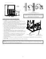
To vent the unit through the wall, connect the pipe
adapter to the exhaust motor adapter. If the exhaust
adapter is at least 24 in.(609mm) above ground level, a
straight section of pellet vent pipe can be used through
the wall.
Your heater dealer should be able to provide you
with a kit that will handle most of this installation,
which will include a wall thimble that will allow the
proper clearance through a combustible wall. Once
outside the structure, a 3 in.(76mm) clearance should
be maintained from the outside wall and a clean out
tee should be placed on the pipe with a 90-degree
turn away from the house. The Clean out tee must be
placed at the bottom of the vertical section of venting,
NOT in the horizontal section. At this point, a 3ft (0.91m)
(minimum) section of pipe should be added with a
horizontal cap, which would complete the installation
(see FIGURE 7).
A support bracket should be placed just below the
termination cap or one every 4ft (1.22m) to make the
system more stable. If you live in an area that has heavy
snowfall, it is recommended that the installation be
taller than 3ft (0.91m) to get above the snowdrift line.
This same installation can be used if your heater is below ground level by simply adding the clean-out section and
vertical pipe inside until ground level is reached. With this installation you have to be aware of the snowdrift line,
dead grass, and leaves. We recommend a 3ft (0.91m) minimum vertical rise on the inside or outside of the house.
The “through the wall” installation is the least expensive and simplest installation. Never terminate the vent under
a deck, in an alcove, under a window, or between two windows. We recommend Simpson Dura-Vent® or Metal-
Fab® kits.
Through the roof/Ceiling Installation
When venting the heater through the ceiling, the pipe is connected the same as through the wall, except the
clean-out tee is always on the inside of the house, and a 3 in.(76mm) adapter is added before the clean-out tee.
The Clean out tee must be placed at the bottom of the vertical section of venting, NOT in the horizontal section.
You must use the proper ceiling support flanges and roof flashing (supplied by the pipe manufacturer; follow the
pipe manufacturer’s directions). It is important to note that if your vertical run of pipe is more than 12ft (3.7m),
the pellet vent pipe size should be increased to 4 in. (102mm) in diameter coming from the back of the stove.
Do not exceed more than 4ft (1.22m) of pipe on a horizontal run and use as few elbows as possible. If an offset
is required, it is better to install 45-degree elbows rather than 90-degree elbows.
OUTSIDE AIR SUPPLY (OPTIONAL, UNLESS INSTALLING IN A MOBILE HOME)
Adequate ventilation air is required to operate this heater. During operation, the heater draws air for combustion
which can be assisted by the installation of outside combustion air inlets. However, certain weather conditions
such as icing or use of kitchen exhaust fans may impact and reduce the effectiveness of vents. It is important to
note that room air starvation will negatively impact the operation of the heater.
Depending on your location and home construction, outside air may be necessary for optimal performance.
Metal pipe (solid or flexible) must be used for the outside air installation. PVC pipe is NOT approved and should
NEVER be used.
A wind shield over the termination of the outside air pipe or a 90-degree elbow or bend away from the prevailing
winds MUST be used when an outside air pipe is installed through the side of a building. The outside air termination
MUST be at least 1ft (0.305m) away from the exhaust system termination.
The outside air pipe on your heater is 2” (50.8mm) OD. The outside air connecting pipe must be at least 2”
(50.8mm) ID. The outside air connection used MUST NOT restrict the amount of air available to your heater. The
outside air connecting pipe must be as short and free of bends as possible, and it must fit over, not inside, the
outside air connection to the heater.
FIGURE 7
TYPICAL THROUGH THE WALL INSTALLATION

