background image

-5-

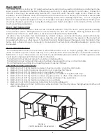
FLOOR PROTECTION

This heater must have a non-combustible floor protector (ember protection) installed beneath it if the floor is 

of combustible material.  If a floor pad is used, it should be UL listed or equal.  The floor pad or non-combustible 

surface should be large enough to cover at least the area under the product and 6 in. (152 mm) beyond the front 

and beyond each side of the fuel loading and ash removal openings. 

Floor protection must extend under and 2 in. 

(50.8mm)  to each side of the chimney tee for an interior vertical installation (see FIGURE 2).

Canadian Installations require a minimum of 450 mm [17.7”] beyond the front of the unit and 200mm [7.8”] 

beyond each side of the unit. A Floor Protector of ¼ inch thick is recommended for this installation.

FIGURE 1

Through the wall installation

FIGURE 2

Interior vertical installation

VENTING REQUIREMENTS

• 

Install vent at clearances specified by the vent manufacturer. 

•  Do not connect the pellet vent to a vent serving any other appliance or stove.

• 

Do not install a flue damper in the exhaust venting system of this unit.

The following installation guidelines must be followed to ensure conformity with both the safety listing of this stove and to 

local building codes. Do not use makeshift methods or compromise in the installation.

MAXIMUM VENTING DISTANCE

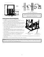
Installation MUST include at least 3-feet of vertical pipe outside the home.  This will create some natural draft to 

reduce the possibility of smoke or odor during appliance shutdown and keep exhaust from causing a nuisance 

or hazard by exposing people or shrubs to high temperatures.  The maximum recommend vertical venting height 

is 12-feet for 3-inch type “PL” vent. Total length of horizontal vent must not exceed 4-feet.  This could cause back 

pressure.  Use no more than 180 degrees of elbows (two 90-degree elbows or two 45-degree elbows and one 

90-degree elbow, etc.) to maintain adequate draft.

IMPORTANCE OF PROPER DRAFT

Draft is the force which moves air from the appliance up through the chimney. The amount of draft in your 

chimney depends on the length of the chimney, local geography, nearby obstructions and other factors. Too 

much draft may cause excessive temperatures in the appliance. Inadequate draft may cause backpuffing into 

the room and ‘plugging’ of the chimney. Inadequate draft will cause the appliance to leak smoke into the room 

through appliance and chimney connector joints. An uncontrollable burn or excessive temperature indicates 

excessive draft. Take into account the chimney’s location to insure it is not too close to neighbors or in a valley 

which may cause unhealthy or nuisance conditions.

IMPORTANT! 

 This unit is equipped with a negative draft system that pulls air through the burn pot and pushes the 

exhaust out of the dwelling. If this unit is connected to a flue system other than the way explained in this manual, it will 

not function properly and will void warranty.

Summary of Contents for Vogelzang VG5790

Page 1: ...installation be completed by a qualified heating equipment installer Refer to markings on stove labels for additional information Contact your local building or fire officials about obtaining permits...

Page 2: ...e unit or within the space required for refueling and ash removal Doing so could result in a house fire Do not over fire or use volatile fuels or combustibles Doing so may cause personal and property...

Page 3: ...feed pellets under these circumstances and a safety concern may arise from sparks or fumes entering the room Allow the stove to cool before performing any maintenance or cleaning Ashes must be dispose...

Page 4: ...UNIT TO ANY AIR DISTRIBUTION DUCT OR SYSTEM The use of other components other than stated herein could cause bodily harm heater damage and void your warranty IMPROPER INSTALLATION The manufacturer wil...

Page 5: ...vertical pipe outside the home This will create some natural draft to reduce the possibility of smoke or odor during appliance shutdown and keep exhaust from causing a nuisance or hazard by exposing...

Page 6: ...vent pipe is designed to disassemble for cleaning and should be checked several times during the burning season Pellet vent pipe is not furnished with the unit and must be purchased separately PELLET...

Page 7: ...ut tee is always on the inside of the house and a 3 in 76mm adapter is added before the clean out tee The Clean out tee must be placed at the bottom of the vertical section of venting NOT in the horiz...

Page 8: ...e paint or protective coating to ensure grounding Vent must be 3 or 4 inch PL Vent and must extend a minimum or 36 in 914mm above the roof line of the mobile home and must be installed using a UL list...

Page 9: ...ode C C F Button The C F button changes the two digit display from degrees Celsius to degrees Fahrenheit D MODE M T BUTTON The Mode of the stove can be switched between manual and controlled with a Th...

Page 10: ...d will not increase heat output but may seriously impair the stoves performance by generating considerable smoke Do not burn wet pellets The stove s performance depends heavily on the quality of your...

Page 11: ...he On Off button to re start your stove The stove will have to fully shut down and turn off before you will be able to restart the stove ROOM AIR FAN When starting your stove the Room Air Fan will not...

Page 12: ...ected by a qualified person annuallyorpertonofpelletstodetermineifacreosoteorflyashbuild uphasoccurred Ifcreosotehasaccumulated it should be removed to reduce the risk of a chimney fire Inspect the sy...

Page 13: ...to clean fly ash out of the heat exchanger The cleanouts are located inside the cabinet doors on the lower front corners of the heat exchanger To access these clean outs you must remove both side pan...

Page 14: ...you need to replace the glass Do not attempt to operate the unit with broken glass Replacement glass may be purchased from your U S Stove Pellet Burning Room Heater Dealer If glass is broken follow t...

Page 15: ...uctions for doing so are given in this manual All other work should be done by a trained technician Trouble Shooting Guide Display is Flashing E1 Possible Causes Possible Remedies Unplug stove first w...

Page 16: ...the stove comes on and works you need to replace the POF thermodisc This is for testing only DO NOT LEAVE THE THERMODISC BYPASSED Your blowers will never shut off and if the fire went out the auger wi...

Page 17: ...ate the bottom end of the auger shaft up towards you until you can lift the shaft out of the stove After you have removed the shaft inspect it for bent flights burrs or broken welds Remove any foreign...

Page 18: ...reviously for the POF thermodisc 2 Bad Auger Motor Remove the auger motor from the auger shaft and try to run the unit If the motor will turn the shaft is jammed on something If the motor will not tur...

Page 19: ...E HAS BEEN ON FOR A WHILE THE BURNPOT OVERFILLS Possible Causes Possible Remedies Unplug stove first when possible 1 Stove or vent pipe is dirty which restricts airflow through the burnpot Follow all...

Page 20: ...20 88177 Gasket Ash Clean Out 2 21 892191 Ash Clean Out Covers 2 22 892245 Weldment Hinge Plate 1 23 892246 Door Assembly 1 24 892247 Skirt 1 25 892248 Top Weldment 1 26 891148 Lid Latch 1 27 892249 G...

Page 21: ...25 26 27 4 3 11 10 12 15 16 14 5 22 24 19 In order to maintain warranty components must be replaced using original manufacturers parts purchased through your dealer or directly from the appliance manu...

Page 22: ...Drive Motor 1 5 rpm ccw 1 N S 891123 Anti Seize Copper A R In order to maintain warranty components must be replaced using original manufacturers parts purchased through your dealer or directly from t...

Page 23: ...23 Wiring Diagram CORRECT WRONG Insure the wires are connected to the bottom two prongs of the hopper switch as shown...

Page 24: ...Name License No Company Telephone No Stove Inspected Chimney Swept Items Replaced Service 05 Date Engineer Name License No Company Telephone No Stove Inspected Chimney Swept Items Replaced Service 07...

Page 25: ...nge Veuillez conserver ce guide dans un endroit sur pour vous y referer Lorsque vous nous crivez veuillez indiquer le num ro complet du mod le affich sur la plaque signal tique de l appareil de chauff...

Page 26: ...r N de licence Compagnie N de t l phone Po le Inspect Chemin e balay e Articles Remplac Service de 05 Date Nom de l ing nieur N de licence Compagnie N de t l phone Po le Inspect Chemin e balay e Artic...

Page 27: ...26 Sch ma de c blage CORRECT FAUX Assurez vous que les fils sont connect s aux deux broches inf rieures de l interrupteur de la tr mie comme illustr...

Page 28: ...Qty 46 83529 Goupille De Moteur De Tari re 1 47 891164 Bo tier De Tari re 1 48 69514 Manchon D agitateur 1 49 891161 Plaque De Fond De Retenue 1 50 891195 Support De Fixation Du Moteur De Tari re 1 5...

Page 29: ...24 Sch ma des pi ces 33 23 32 31 21 17 8 2 1 18 8 21 20 9 13 37 35 34 36 7 44 29 6 38 30 28 25 26 27 4 3 11 10 12 15 16 14 5 22 24 19...

Page 30: ...ouvercles De Nettoyage Des Cendres 2 21 892191 Couvercles De Nettoyage Des Cendres 2 22 892245 Weldment Plaque De Charni re 1 23 892246 Dispositif De Porte 1 24 892247 Basque 1 25 892248 l ment Sup ri...

Page 31: ...fix e la tige du registre d admission Lorsqu on d place la tige du registre la plaque doit se d placer avec elle 6 Blocage du conduit d admission d air Inspecter visuellement le conduit d admission d...

Page 32: ...r pouvoir examiner l arbre de la tari re Soulevez l g rement l arbre de la tari re de sorte que l extr mit de l arbre sorte du manchon inf rieur de tari re Retirez ensuite les deux crous qui tiennent...

Page 33: ...Si la tension est inf rieure la valeur nominale v rifiez le c blage Si le c blage est bon c est le tableau qui est d fectueux L INTERRUPTEUR DE SURCHAUFFE SE D CLENCHE TOUT LE TEMPS Causes possibles...

Page 34: ...arbre de la tari re de sorte que l extr mit de l arbre sorte du manchon inf rieur de tari re Retirez ensuite les deux crous qui tiennent la pastille sup rieure de la tari re Puis faites pivoter l extr...

Page 35: ...tari re Retirez les deux boulons du c t du tube de tari re pour d poser le roulement inf rieur de la tari re Tirez sur la tari re pour la sortir du tube afin de lever le blocage 7 Le moteur de la tari...

Page 36: ...7 Le tableau de commande n envoie pas le courant au ventilateur de combustion Si l alimentation lectrique n arrive pas au ventilateur de combustion v rifiez toutes les connexions des fils lectriques...

Page 37: ...che E1 clignotant Causes possibles Solutions possibles D branchez le po le avant toute chose quand c est possible 1 Le ventilateur de convection surchauffe et d clenche l arr t de temp rature interne...

Page 38: ...d vacuation Nettoyez tous les filtres du syst me d vacuation et du tuyau d entr e d air ext rieur Activez toutes les commandes et v rifiez qu elles fonctionnent correctement C est aussi le bon moment...

Page 39: ...OID AU TOUCHER AVANT ASPIRATION Certains aspirateurs peuvent fuir les cendres dans la pi ce Votre aspirateur devrait avoir un filtre sp cial ou un sac pour liminer les fuites 5 Retirer la casserole de...

Page 40: ...changeur de chaleur Pour acc der ces outs propres vous devez retirer les deux panneaux lat raux Les sorties propres sont fix es la chambre de combustion avec 2 vis 5 16 Retirez les feuilles propres et...

Page 41: ...diqu peut entra ner une baisse des performances et un risque pour la s curit D branchez le cordon lectrique du po le avant de retirer le panneau arri re ou d ouvrir le syst me d vacuation pour toute t...

Page 42: ...tion de l aspect de la flamme Une flamme basse rouge tre peut tre am lior e en tournant l g rement le registre vers la droite Une flamme en torche peut tre am lior e en tournant l g rement le registre...

Page 43: ...iment pour lesquels le po le a t approuv et cela annulerait toutes les garanties La conception du po le int gre l alimentation automatique des granul s dans le feu selon un rythme soigneusement calcul...

Page 44: ...rres passant du niveau 1 au niveau 5 de chauffage C TOUCHE C F La touche C F fait passer l affichage deux chiffres des degr s Celsius aux degr s Fahrenheit et vice versa D TOUCHE MODE M T Le Mode de f...

Page 45: ...air ext rieur et votre concessionnaire pour l achat V rifiez aupr s de votre municipalit si d autres codes sont applicables Prise d air frais Sortie d chappement 878mm 34 56po 108mm 4 24po 321mm 12 63...

Page 46: ...t s fournis par le fabricant de conduits suivez les instructions du fabricant Il est important de noter que si la longueur de tuyau vertical est sup rieure 12 pi 3 7 m la taille du conduit d vacuation...

Page 47: ...r une vacuation de 4 po si sa hauteur doit d passer 12 pi 3 66 m ou si l installation se trouve plus de 2 500 pi 762 m d altitude Nous recommandons l utilisation de conduits Simpson Dura Vent ou Metal...

Page 48: ...en respectant les d gagements sp cifi s par le fabricant d vacuations Ne reliez pas l vacuation pour po le granul s une vacuation utilis e pour un autre appareil ou un autre po le N installez pas de r...

Page 49: ...L utilisation de composants autres que ceux qui sont indiqu s ici pourrait provoquer des blessures endommager le po le et annuler la garantie INSTALLATION INAD QUATE Le fabricant ne pourra tre tenu p...

Page 50: ...er le po le lorsque la porte d observation est ouverte Dans ce cas la tari re ne distribue pas les granul s et un probl me de s curit peut se poser en raison des tincelles ou des fum es p n trant dans...

Page 51: ...remplissage des granul s et l enl vement des cendres Cela pourrait d clencher un incendie dans la maison Ne surchauffez pas et n utilisez pas de carburant ou combustible volatile cela pourrait provoqu...

Page 52: ...ls des blessures corporelles ou m me la mort Remarque Il est recommand que l installation soit compl t e par un installateur d quipement de chauffage qualifi Reportez vous aux marquages sur les tiquet...

Reviews: