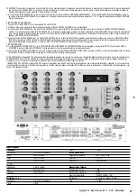
INSTRUCTION MANUAL - PROFESSIONAL MIXER - USB 7100
Features:
*. 4 Stereo Channels
*. State of the Art Cue Section
*. 3 Phono/Line Convertible, 5 Line, and 2 Mic Inputs
*. 3 band (LOW MID HI) EQ for each channel
*. Talkover
*. Master, Booth and Record outputs
*. Digital Sampler with 5 Memory Banks
*. Battery backup to retain samples
Connections:
1. Before plugging in the power cord, make sure that the VOLTAGE SELECTOR (53) switch is set to the correct voltage.
NOTE: This product is double insulated and not intended To be grounded.
2. Make sure that the POWER (47) switch is the off position. The POWER LED (48) will be off.
3. The USB 7100 is supplied with 3 sets of amp output jacks. The MAIN OUTPUT (55) jacks are unbalanced and used to connect to your main amplifier. The REC OUTPUT
(56) jacks allow you to hook up an Additional amplifier.
4. The MIC 1(1) input (found on the front panel) accepts 1/4" or XLR connector. The MIC 2(69) input (found on the rear panel) accepts 1/4" connectors. ALL accept balan-
ced and unbalanced microphones. On the real panel are 3 stereo PHONO/LINE (62,65,68) inputs and 5 stereo LINE (58,59,60,63,66) inputs. The PHONO/LINES SWITCH
(62) enables you to set he (61) input to phono Line. The PHONO/LINE SWITCH (65) enables you to set the (65)input to Phono or Line.
The PHONO/LINE SWITCH (68) enables you to set the (67) input to phono or Line. The phono inputs will accept only turntables with a magnetic cartridge. A GROUND
SCREW(70)for you to ground your turntables is located on the rear panel. The Stereo Lin inputs will accept any line level input such as a CD player, et e.75. Headphones
can be plugged into the front panel mounted HEADPHONE (52) jack7 The USB 7100 comes with a front panel BNC LIGHT (46) jack. This jack is for use with a gooseneck
light.
Using the Ground Life Switch:
Depending on your system configuration, sometimes applying the Ground will create a quieter signal path. Sometimes lifting the ground Can eliminate ground loops and hum
to create a quieter signal path.
1. With the mixer on, listen to the system in idle mode (no signal present) with the ground applied (the GROUND LIFT SWITCH (70) in The left position)
2. Then turn the power off before moving the GROUND LIFT SWITCH (70). Lift the ground by moving the GROUND LIFT SWITCH to the right Turn the power back on and
listen to determine which position will provide a signal devoid of background noise and bum. Keep the GROUND LIFT SWITCH in the ground position if the noise level
remains the same in either position.
CAUTION: DO NOT TERMINATE THE AC GROUND ON THE POWER MIXER IN ANY WAY. TERMINATION OF THE AC GROUND CAN BE HAZARDOUS.
Operation:
1. POWER ON: Once you have made all the equipment connections to your mixer, press the POWER SWITCH (47). The power will turn on and the POWER LED (48) will
glow RED.
2. CHANNEL 1:Switch # (17) allows you to select the PHONO 1/LINE 1(67) or the LINE (2) 66 input. The GAIN (7) and CHANNEL SLIDE (12) controls the input level of this
channel. The EQ CUT (9,0,10) to allow you to adjust the sound.
3. CHANNEL 2:Switch # (17) allows you to select the PHONO 2/LINE 3 (64) or the LINE 4 (63) input. The GAIN (13) and CHANNEL SLIDE (18) controls the input level of
this channel. The EQ CUT (14,15,16) to allow you to adjust the sound.
4. CHANNEL 3:Switch # (23) allows you to select the PHONO 3/LINE 5(61) or the LINE 6 (60) input. The GAIN (19) and CHANNEL SLIDE (24) controls the input level of
this channel. The EQ CUT (20,21,22) to allow you to adjust the sound.
5. CHANNEL 4:Switch # (29) allows you to select the LINE 7 (59) or the LINE 8 (58) input. The GAIN (25) and CHANNEL SLIDE (30) controls the input level of this chan-
nel. The EQ CUT (26,27,28) to allow you to adjust the sound.
6. CROSSFADER SECTION: The CROSSFADER (32) allows the mixing of one source into another. The USB 7100 features an assignable crossfader. The ASSIGN (31,33) swit-
ches allow you to select Which channel will play through each side of the crossfader. The ASSIGN (31) switch has 5 settings (OFF,1,2,3.Or 4) and allows you to select
channel 1,2,3 or 4) and allows you to select channel 1,2,3,4 to play through the right side of the crossfader. With the ASSIGN switch in the off position. That side of the
crossfader will be inactive. The CROSSFADER (32) in your unit is removable and if need arises can be easily replaced.
7. OUTPUT CONTROL SECTION: The level of the MAIN OUTPUT (55) is controlled by the MASTERT (38) slide. Activating the MONO (37) button (the mono LED will light )
makes the overall output mono. The BOOTH (49) control adjusts the level of the BOOTH PUTPUT (56). HINT: The BOOTH OUTPUT is used by some Djs to run monitor spe-
akers in their Dj booth. You can also use it as a second ZONE or AMP output
NOTE: The REC OUTPUT (57) has no level control. The level is set by the channel gain or slides or the selected channel.
8. TALKOVER SECTION: The purpose of the talkover section is to allow the program playing to be muted so that the mic can be heard above the music. The MIC/TALKOVER
SWITCH (6) controls MIC 1 And MIC 2 and has three settings. When the MIC/TALKOVER SWITCH (6) is in the bottom position. MIC 1 and MIC 2 and talkover are off.
When the MIC/TALKOVER SWITCH (6) is in the center Position MIC 1 and MIC 2 are on, but talkover is off. When the MIC/TALKOVER SWITCH (6) is in the top position.
MIC 1 and MIC 2 and talkover will be on and the volume of all sources except the Mic input are lowered by 16 dB. The TREBLE (4) and BASS (5) controls allow you to
fully adjust the tone Of MIC 1 and MIC 2. MIC 1 LEVEL (1) controls the level of MIC 1. The MIC 2 LEVEL (2) controls the level of MIC 2.
9. CUE SECTION: By connecting a set of headphones to the HEADPHONE (52) jack, you can monitor any or of the channels, Press the CUE/SAMPLE ASSIGN (35) buttons
for channels 1-4 to Select the channel or channels to be monitored and their respective LED indicators will Red. Press the CUE/SAMPLE ASSIGN (34,35) buttons are also
used to adding samples (see sampler operation for more details). Press the CUE SAMPLER (39) to monitor samples. Use the CUE LEVEL (51) control to adjust the cue
volume without effecting the overall mix. By moving the CUE PGM PAM (50) control to the left you will be able to monitor the assigned cue signal. Moving the control to
the right will , monitor the PGM (program) output.
10. DISPLAY: The DISPLAY (36) indicates either the MASTER output left and right levels.
Sampler Operation:
1. GENERAL INFORMATION: The USB 7100 sampler uses Dynamic RAM Memory and a 16 bit microprocessor controller. The full bandwidth results in sound reproduction.
Results in true sound reproduction.
2. MWMORY INFORMATION: The USB 7100 comes equipped with five MEMORY BANKS (44). The two banks marked 2 &2 are two seconds in length, the two banks mar-
ked 4&4 are four seconds in length and the bank marked 12 is twelve seconds in length. These banks are separate and can not be linked. You can store a different sample
in each bank but they must be recorded individually and they must be played one at a time
SAMPLE RECORDING:
1. Put the MODE SELECTOR (43) switch into the WRITE position.
Select the source you want to sample from by pressing the appropriate CUE/SAMPLE ASSIGN (34,35) button. Select the memory bank you want to record into, by pressing
the proper MEMORY BANK (44) button.
2. The USB 7100 comes equipped with a sampler PITCH (41) control. To set a perfect sample, set the control to its center position and record the sample. During playback,
raising or lowering the control will raise or lower the pitch of the sample playback. The center position will remain as normal pitch
4
Copyright U.S. Blaster Europe BV © - Delft - Netherlands
ENG

