E N G L I S H
65
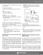
right side of the display.
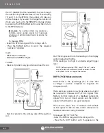
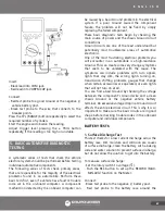
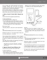
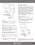
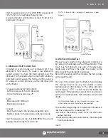
Insert:
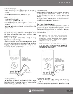
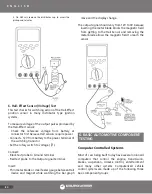
• Black lead in COM jack.
• Red lead in VΩRPM CAP jack.
Connect:
- Black test probe to a good Ground at the carburetor
or the negative (-) vehicle battery post.
- Red test probe to the solenoid signal.
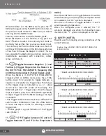
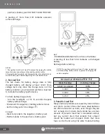
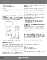
Press the ± TRIG button for 2 seconds to toggle
between the negative (-) and positive (+) slope.
Start the engine. A DUTY-CYCLE of approximately
50% should be read.
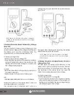
Adjust the trigger level pressing the ± TRIG button
repeatedly if reading is too high or unstable.
Most cars have the points of the solenoid closed for a
DUTY-CYCLE between 50 and 70%.
Once the engine warms up and goes into open loop,
the DUTY-CYCLE should fluctuate.
NOTE: Consult the car’s service manual to verify slope
assigned to position for each component.
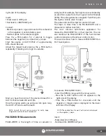
PULSE-WIDTH Measurements
PULSE-WIDTH is the length of time an actuator is
energized. For example, fuel injectors are activated by
an electronic pulse from the Engine Control Module
(ECM). This pulse generates a magnetic field that pulls
the injector nozzle valve to open.
The pulse ends and the injector nozzle is closed.
This Open to Close time is the PULSE-WIDTH and is
measured in milliseconds (mS).
The most common automotive application for
measuring PULSE-WIDTH is on fuel injectors. You can
also measure the PULSE-WIDTH of the fuel mixture
control solenoid and the idle air control motor.
This exercise shows how to measure PULSE-WIDTH on
Port Fuel Injectors.
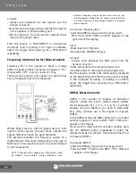
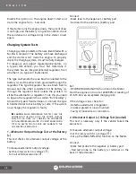
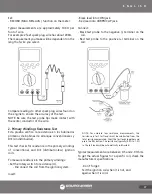
To measure PULSE-WIDTH (mS):
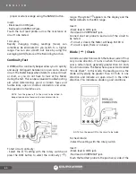
- Select the RPM IG range with the rotary switch.
- Press the % DUTY button until mS appears on the
right side of the display.
- Press the ± TRIG button for 2 seconds until the
negative (-) trigger slope is displayed on the lower
left side of the display.
NOTE: The applied time for most fuel injectors is displayed
on the negative (-) slope.
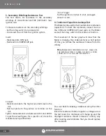
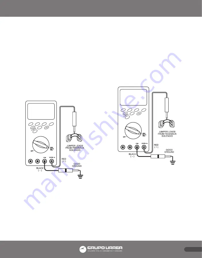
Insert:
- Black lead into COM jack.
- Red lead into VΩRPM CAP jack.
Summary of Contents for UD88
Page 94: ...94 NOTAS NOTES ...
Page 95: ...95 NOTAS NOTES ...

