E N G L I S H
62
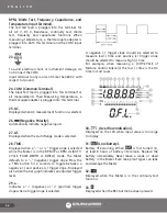
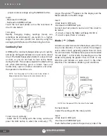
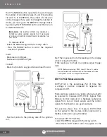
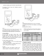
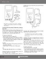
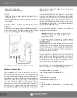
TEMP VΩRPM CAP and COM jack.
Touch the end of K-type thermocouple to the area or
surface of the object to be measured.
NOTE: To avoid error, it is very important to use a
thermocouple adaptor whose materials match the
thermocouple you are using.
Capacitance (CAP) Measurements
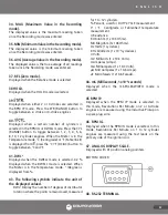
CAUTION: TURN THE POWER OFF TO THE CIRCUIT TO
BE TESTED. DISCHARGE THE CAPACITOR BY SHORTING
THE CAPACITOR LEADS TOGETHER. USE THE DC VOLTS
FUNCTION TO CONFIRM THAT THE CAPACITOR IS
DISCHARGED.
NOTES:
1.- Holding the probes with your hands may charge the capacitor in
circuit and generate a false reading.
2.- Residual voltage charges on the capacitor, poor insulation
resistance or poor dielectric absorption may cause measurement
errors. If more discharge is necessary, the Meter displays “
”
while the capacitor is discharging.
3.- In 1μF range, the readings are probably unstable due to
environmentally induced electrical noise and floating capacity of
the test leads. Therefore, directly connect the capacitor to the input
terminals.
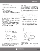
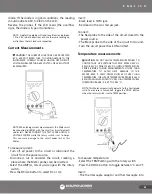
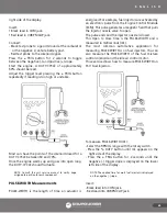
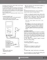
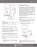
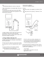
To measure capacitance:
- Select the Capacitance (CAP) setting with the rotary
switch.
- The Meter will automatically select a suitable range
from 1μF to 1000 μF.
Insert:
- Black lead in COM jack.
- Red lead in VΩRPM CAP jack.
Touch the test probes to the capacitor and read the
display.
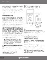
When measuring polarized capacitors, connect the
positive to the VΩRPM CAP jack and the negative to
the COM jack.
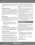
Hi-Sen* Frequency (Hz) Measurements
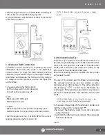
The Meter has two frequency measurement modes:
The Hi-Sen* (stands for High Sensitivity – Approximate
Trigger Level: 150mV) mode for the general frequency
counter mode and the Hz of RPM IG mode for the
automotive measurement.
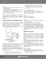
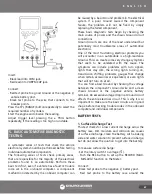
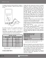
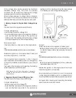
In the Hi-Sen Frequency counter mode, the Meter
autoranges to one of four ranges: 199.99Hz, 1999.9Hz,
19.999KHz and 199.99KHz.
If the input signal is below the trigger level, frequency
measurement will not be taken. If your readings are
unstable, the input signal may be near the trigger
level for that range. You can usually correct this by
selecting a lower range using the RANGE button.
If your readings seem to be a multiple of what you
expected, your input signal may have distortion or
ringing like the signals from electronic motor controls.
Summary of Contents for UD88
Page 94: ...94 NOTAS NOTES ...
Page 95: ...95 NOTAS NOTES ...

