background image


11/2015 

NT  BEA-G6EVO 

V3.0 

EN 

p. 32/58 


5.2. COMMON CHECK POINTS DETAILS 
 

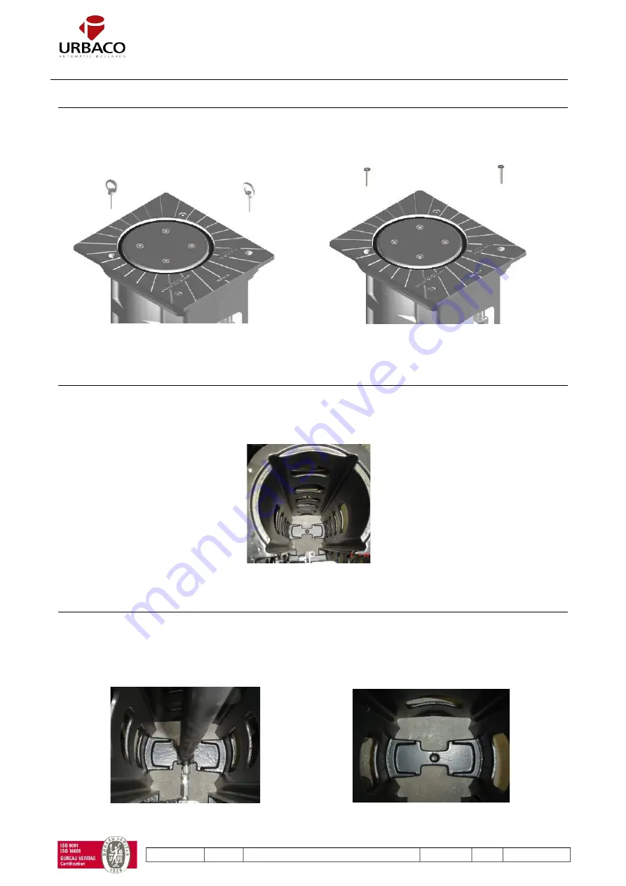
5.2.1. Cover well fastened – Check Point N°1 


Remove  the  hoisting  rings,  clean  the  casing  threading  holes  (using  compressed  air)  and  apply  grease  (Molykote 
CU7439 Molykote or equivalent) before placing back the screws. Firmly tighten all screws. 


5.2.2. Guides are cleaned – Check Point N°2 


Make  sure  the  casing's  guides  and  the  bollard  head  guides  are  cleaned  and  freed  from  deposits.  Before  reassembling 
the bollard, spray the guides with Molykote 3402C or equivalent lubrication.  


5.2.3. Cylinder well positioned – Check point N°3 


NOTE: to perform this action, remove the cover and action the bollard in the raised position (without dismantling the 
bollard head).  

Check that the cylinder is properly centred in the cross-bar on the bottom of the casing. 


Figure 36: Guide rails view


Figure 38: Casing crossbar


Figure 37: Cylinder position


Figure 35: Put the two screws back in place


Figure 34: Remove the two hoisting ring


Summary of Contents for G6EVO

Page 1: ...11 2015 NT BEA G6EVO V3 0 EN p 1 58 INSTALLATION AND OPERATION MANUAL G6 EVO AUTOMATIC RETRACTABLE BOLLARD ...

Page 2: ...4 1 Bollard positioning 22 3 4 2 Bollard position marks and excavation 23 3 4 3 Building the draining system 24 3 4 4 Positioning the lost casing if used 25 3 4 5 Pour the concrete foundation 25 3 4 6 Checking the capacity of the lost casing or the excavation to receive the bollard 26 3 4 7 Positioning the bollard 26 3 4 8 Leveling and finishing the final top layer 27 3 5 Connections 27 3 5 1 Run ...

Page 3: ...ing system changing 41 6 2 6 Magnet changing 42 6 3 Pneumatic motorization corrective actions details 42 6 3 1 Cover and or covering sleeve and or top plate changing 42 6 3 2 Pneumatic cylinder changing 43 6 3 3 Pneumatic compnents bracket changing 43 6 4 Standard hydraulic motorization corrective actions details 44 6 4 1 Limitswitch sensors changing 44 6 4 2 Hydraulic cylinder changing 44 6 4 3 S...

Page 4: ...wing Directives 2004 108 CE Electromagnetic Compatibility Directive CEM 2006 95 CE Low Voltage Directive And that it is forbidden to commission the bollard until the machinery into which it will be integrated or of which it will become a component is identified and until the declaration of conformity to the conditions established by Directive 2006 42 CE As well as the following regulations NF P 98...

Page 5: ... negligence or accident 3 No non approved by URBACO components have been used NO OTHER WARRANTY IS EXPRESSED AND NONE SHALL BE IMPLIED INCLUDING WITHOUT THE WARRANTY OF MERCHANTABILITY OR WARRANTY OF FITNESS FOR USE THE FOREGOING STATES THE ENTIRE LIABILITY OF URBACO WITH RESPECT TO THE PRODUCTS IN NO EVENT SHALL URBACO BE LIABLE FOR ANY SPECIAL INCIDENTAL OR CONSEQUENTIAL DAMAGES WHICH RESULT FRO...

Page 6: ... bollard when it is moving Do not work close to bollards in movement Do not touch the moving element while it is in movement Do not obstruct the operator s movements as this could result in hazardous situations Please prevent unauthorized persons from accessing to the retractable bollards manoeuvre field and also prevent them to activate the fixed control actuators Keep also any remote control dev...

Page 7: ...other use is considered improper and therefore dangerous Any use other than the one described in this manual is forbidden URBACO declines any liability in case of improper use of the system URBACO declines any liability as concerns the security and proper functioning of the operator if non URBACO components are used unless otherwise stated in writing by URBACO Never modify the original components ...

Page 8: ...so URBACO suggests that you first establish the position of the loops then the bollards and lastly the technical control unit Recommendations to respect the proper use of an access point that is controlled by automatic retractable bollards To ensure proper functioning of the access point URBACO suggests To install a vertical sign that warns people of the obstruction and that reads Retractable boll...

Page 9: ...tance and an intensive rate of use Also the G6EVO bollard maintenance is limited due to the use of simple and sturdy elements The bollard is made up of 1 Cast iron casing 2 Cast iron bollard head 3 Painted cast iron cover 4 Cylinder 5 Removable components bracket 6 Bollard covering Top plate and sleeve Figure 1 Example of a G6EVO Ø250 H750 Chateauneuf version with LED light ring light diffusers on...

Page 10: ...and maintenance O Standard anti freeze device up to 20 C 1 O High anti freeze device up to 50 C 1 O Movement warning sound buzzer 1 O Lost casing O C Multiple Choice O Optional 1 Involved changes and or additional components into the technical control unit The multiple choices C are detailed in 2 5 Option O are detailed in 2 6 Figure 5 Top plate with screws and light diffusers Figure 3 Motorizatio...

Page 11: ...H750 Ø250 H550 Ø200 H750 Motorization Pneumatic Hydraulic standard Built in hydraulic Pneumatic Hydraulic standard Pneumatic Hydraulic standard Built in hydraulic Code BPEVOF75 BHEVOF75 BHEEVOF75 BPEVOF55 BHEVOF55 BPEVOE75 BHEVOE75 BHEEVOE75 Bollard power supply 24 V 50 Hz 24 V 50 Hz and 230 V 60 Hz 24 V 50 Hz 24 V 50 Hz 24 V 50 Hz and 230 V 60 Hz Operating pressure 7 bar 35 bar 35 bar 7 bar 35 ba...

Page 12: ...bollard can be configured using the following codes 4 to 5 codes are necessary to fully set a G6 EVO Bollard 1 Code to choose bollard motorization and size 2 Code to choose bollard covering sleeve 3 Code to choose LED light ring 4 Code to choose Top plate appearance Codes are detailed in 2 5 2 1 2 3 4 5 Figure 8 G6EVO Bollard configuration code exploded view ...

Page 13: ...HF75 VDM Stainless Steel Sleeve for G6EVO Bollard Ø250 H750 BO EVO H F 75 VDM Bollard Option Product family EVO G6EVO Option type H Habillage sleeve Bollard diameter E Ø200mm F Ø250mm Bollard Height above ground 50 500mm 55 550mm 75 750mm Covering type CL Cylinder VDM Vendôme CHP Chateauneuf CUSxxx Customized BP EVO F 75 Motorization BP Pneumatic BH Hydraulic standard BHE Built in Hydraulic Produc...

Page 14: ...D 4 Choose top plate appearance Example BOEVOCFAV Steel top plate with visible screws and no diffusor BO EVO C F AV Bollard Option Product family EVO G6EVO Option type C Chapeau top plate Bollard diameter E Ø200mm F Ø250mm Appearance type AV Painted Steel visible screws AVD Painted Steel visible screws light diffuser IV Stainless Steel visible screws IVD Stainless Steel visible screws light diffus...

Page 15: ...ight color only when led light option code finish by CL Example BOEVOSCLGR Green led light BO EVO S CL GR Bollard Option Product family Option type S Signalling system LED light ring LED color choice GR Green YE Yellow PU Purpul BL Bleu CY Cyan WH White ...

Page 16: ... with light diffusers and hidden screws 1 BPEVOF75 Pneumatic G6EVO Bollard Ø250 H750 2 BOEVOHF75CHP G6EVO covering with painted chateauneuf sleeve 3 BOEVOSFCL G6EVO Lid light ring 4 BOEVOID G6EVO Stainless steel top plate with light diffusers and hidden screws 5 BOEVOSCLWH G6EVO LED light color White 1 2 3 4 Figure 9 Example of a G6EVO Ø250 H750 painted Chateauneuf version with white LED light rin...

Page 17: ...ure option means that the bollard remains up if the power is cut off The bollard could then be manually retracted Hoisting kit for installation and maintenance See hoisting security manual NT CGS Standard anti freeze device up to 20 C 1 High anti freeze device up to 50 C 1 Any anti freeze option is easy to install into the bollard Movement warning sound buzzer 1 The sound buzzer will make a sound ...

Page 18: ...nit and each bollard does not exceed 25 meters Check that the maximum length of the twisted connecting cable between the loops and the loop detector does not exceed 50 meters Check that the sheaths between the control unit and the bollards are buried at the legal depth according to the country s laws in force Check that all sheaths are installed without sharp angle to pull through electrical cable...

Page 19: ...solution with a retractable bollard magnetic loops technical control unit and traffic lights Please refer to the manual N NT BCL and NT for all types of installation layouts including specific safety solutions 1 Automatic retractable bollard 4 safety loop 2 Automatic exit loop 5 Technical control unit 3 Safety loop 6 Traffic light 1 3 2 4 6 5 Figure 11 Standard installation skecth ...

Page 20: ...6EVO bollard concrete foundation dimensions It is recommended to install the bollard using concrete foundation as shown below Traffic Way For lost casing dimensions refer to the appendix N COFG6 Lost casing length 200 Lost casing height 200 200 Figure 13 Cross section view of an installed G6EVO bollard with lost casing ...

Page 21: ... its installation 3 3 Unpacking and handling the bollard 3 3 1 Unpacking the bollard Unpacking precautions Before cutting the straps that bind the bollard on the pallet check that the bollard stands stable on the pallet and that the pallet is in good condition considering the bollard s significant weight Each bollard is wrapped at the top and bottom with yellow adhesive tape mentioning Do not remo...

Page 22: ...tion Special recommendations The reinforcing steel rebars must exclusively be of the HLE type TOR steel Rebars fastened must be done with either steel wire or welded The concrete must be carefully checked It should have a density of at least 350 to 450kg of cement per m3and the cure times must be respected at least 28 days for standard concrete To reduce the job duration we suggest using a fast cu...

Page 23: ... where this sheath is buried in must not be too close to the loop s cable never less than 100 mm and must not sharply change of direction The trenches depth must comply with the country s laws in force 3 4 2 Bollard position markings and excavation After defining the position and direction of the bollard trace measurements X and Y of the excavation Then depending on the ground type cut the top lay...

Page 24: ...fill it with gravel up to about 250 mm in height The drainage system must be able to evacuate 20 liters of water in five minutes Place a section of 100 mm diameter PVC pipe and pour the first concrete layer When the ground is not very permeable it is best to link the bottom of the excavation to an additional drainage network system Figure 23 Excavation cut view Figure 24 Drainage with PVC pipe Fig...

Page 25: ...and with respect to the traffic way We suggest using a bubble level 3 4 5 Pour the concrete foundation Steel elements must be covered by at least 5 cm of concrete It is recommanded to vibrate the concrete for a homogeneous fill Figure 27 Wooden reinforcement installed into the lost casing Figure 28 Concrete poured Figure 26 Lost casing installation Figure 29 Reinforcement removed after concrete cu...

Page 26: ...the cover up on the ground surface And this is prohibited If the lost casing is embedded too high the bollard will overhanging the ground surface and creates a dangerous obstacle for pedestians And this is prohibited Clean the surroundings of the excavation Remove anything that may damage the bollard coating Important the height of the concrete foundation must be under the finishing floor level so...

Page 27: ... hydraulic standard solution the hydraulic pump is installed into the technical control unit be very careful with the following two points The hydraulic hose must be run inside the sheath in one single way from the bollard to the technical control unit The U bend end shape of the hose must stand on the bollard side for connection The hydraulic hose must remain as straight as possible to prevent an...

Page 28: ...heath to free up space into the bollard 3 5 3 Technical control unit connections All automatic bollards are supplied with an access control unit This access control unit could be installed independently from the bollard The technical control unit connection will depend on the global solution choosen Here are the controllers compatible proposed by URBACO U200 U202H AT224 LOGO ZELIO Industrial Compu...

Page 29: ...llard to the wire run into the sheath for this purpose The other wire extremity will be connected to the right terminal block refer to the technical control unit documentation Check the oil level in the hydraulic tank Check that there is no oil leak Check that there is no contact between the hydraulic hose and the bollard head Built In Hydraulic Check Points HECP Checked Connect the solenoid valve...

Page 30: ...form depend on the global solution and allocated controller chosen Therefore please refer to the used controller before commissioning the sytem 4 3 REMOVING SITE PROTECTIONS After performing all operating tests with success and making the access point functional and safe the protections and signs can be removed ...

Page 31: ...nth 3rd month 4th month 5th month 6th month 7th month 8th month 9th month 10th month 11th month 12th month 8 PA 5 3 1 No contact between bollard head and pneumatic hose C C C 9 PA 5 3 2 No air leaks C C C 10 PA 5 3 3 Proper solenoid valve connection C C C 11 PA 5 3 4 Components properly fastened onto the bracket C C C Specific yearly maintenance program for the HYDRAULIC STANDARD motorization Chec...

Page 32: ...the bollard head guides are cleaned and freed from deposits Before reassembling the bollard spray the guides with Molykote 3402C or equivalent lubrication 5 2 3 Cylinder well positioned Check point N 3 NOTE to perform this action remove the cover and action the bollard in the raised position without dismantling the bollard head Check that the cylinder is properly centred in the cross bar on the bo...

Page 33: ...ctions on the technical control unit and inside the bollard and if the problem continues replace the limit switch sensor 5 2 5 Solenoid valve control Check point N 5 The solenoid valve must work Check the wiring and connections into the Bollard and inside the technical control unit See appendix NT REVB 5 2 6 Drainage efficiency control Check point N 6 The drainage system must be able to evacuate 2...

Page 34: ...rm preventive maintenance by replacing all screws 5 3 PNEUMATIC MOTORIZATION CHECK POINTS DETAILS 5 3 1 No contact between bollard head and pneumatis hose Check Point N 8 Make sure that the pneumatic hose hasn t moved during the transport The pneumatic hose must stay in center position and have no contact with the bollard head part at any time 5 3 2 No air leak Check Point N 9 Check the air pressu...

Page 35: ... 5 4 STANDARD HYDRAULIC MOTORIZATION CHECK POINTS DETAILS 5 4 1 No contact between bollard head and hydraulic hose Check Point N 12 Make sure that the hydraulic hose hasn t moved during the transport The hydraulic hose must stay in center position and have no contact with the bollard head part at any time Figure 43 Bracket position identification Figure 44 Bracket extraction Figure 45 Bracket posi...

Page 36: ... no contact with the bollard head part at any time It is guided and protected by the hydraulic unit support 5 5 2 No oil leak Check Point N 15 Check that there is no oil leak from the hydraulic hose and the cylinder 5 5 3 Proper solenoid valve connection Check Point N 16 See NT REVB 5 5 4 Tighten up the fastening screws of the hydraulic pump onto support and support onto casing Check Point N 17 Ch...

Page 37: ...ent Specific corrective tasks for the PNEUMATIC motorization Checkpoints Action type Task name 7 CA 6 3 1 Limit switch sensors replacement 8 CA 6 3 2 Cylinder replacement 9 CA 6 3 3 Pneumatic components bracket replacement Specific corrective tasks for the HYDRAULIC STANDARD motorization Checkpoints Action type Task name 10 CA 6 4 1 Limit switch sensors replacement 11 CA 6 4 2 Cylinder replacement...

Page 38: ...so it is necessary to keep the site closed to traffic by fitting legal signage dedicated to this type of construction site Before starting works always check that the power supply has been cut off NT CGS 6 2 COMMON CORRECTIVE ACTION DETAILS 6 2 1 Covering sleeve and or top plate replacement Task N 1 For the visible screws top plate version Figure 51 Bollard retracted Figure 52 Screws and cover rem...

Page 39: ...ure 58 Specific disassembly tool in position Figure 59 Insert the handling tool to catch the sleeve s compression system Figure 60 Push down to free up the sleeve and slide it down Figure 62 When the sleeve has slid down a gap between top plate and sleeve appears Figure 63 Remove the top plate using an Allen key Figure 64 Sleeve removed Figure 61 Handling tool positioning view ...

Page 40: ...er it wears down Remove the old frictionless ring After having scrapped off all glue residues fit the new ring with polyurethane glue 6 2 3 Guide rails cleaning Task N 3 The casing guide rails must be dust free Before reassembling the bollard spray the guides with Molykote 3402C or equivalent lubrication oil Figure 66 dismounted cover and frictionless ring Figure 65 cover with mounted frictionless...

Page 41: ...ding and protected with heat shrinkable sheath or with waterproof electrical connectors 6 2 5 Sleeve holding system replacement Task N 5 To perform this task the bollard head must be cover free and out from the casing See 6 2 1 for more details Figure 69 Top Plate disassembly Figure 70 LED light disassembly Figure 71 Sleeve holding system Figure 72 Take the bottom bolt off Figure 73 Remove the fir...

Page 42: ...es to the access safe functioning The limit switch is a normally open contact The bollard head is equipped with a detection magnet See appendix N NT REG for more detail Check the fastening and positioning of each limit switch sensor they must never touch the magnet Check that they properly detect the bollard when in up and in down position In case of malfunction check the connections on the techni...

Page 43: ...ollard head must be cover free See 6 2 1 for more details See appendix N NT RVP for more detail 6 3 3 Pneumatic components bracket replacement Task N 9 Figure 79 remove the central screw that holds the cylinder Figure 80 remove the cylinder Figure 81 disconnect the cylinder Figure 82 replace components bracket ...

Page 44: ... equipped with a detection magnet See appendix N NT REG for more detail Check the fastening and positioning of each limit switch sensor they must never touch the magnet Check that they properly detect the top and the bottom of the bollard In case of malfunction check the connections on the technical control unit and in the bollard and if the problem continues replace the limit switch sensor 6 4 2 ...

Page 45: ...11 2015 NT BEA G6EVO V3 0 EN p 45 58 6 4 3 Standard hydraulic components braket replacement Task N 12 Figure 86 remove the cylinder Figure 87 disconnect the cylinder Figure 88 Replace components bracket ...

Page 46: ...functioning The limit switch is a normally open contact The bollard head is equipped with a detection magnet Check the fastening and positioning of each limit switch sensor they must never touch the magnet Check that they properly detect the top and bottom of the bollard In case of malfunction check the connections on the technical control unit and in the bollard and if the problem continues repla...

Page 47: ...ee See 6 2 1 for more details See appendix N NT RVH 6 5 3 Hydraulic pump replacement Task N 14 Figure 93 remove the central screw that holds the cylinder Figure 94 remove the cylinder Figure 95 disconnect the cylinder Figure 96 Hydraulic pump support assembly screw identification Figure 97 Unscrew the hydraulic pump support assembly screw ...

Page 48: ... Figure 101 Solenoide valve identification Figure 98 Remove the hydraulic pump from its support and the cylinder Figure 99 Hydraulic pump top assembling screws Figure 100 Hydraulic pump bottom assembling screws Figure 102 Remove the knurled nut Figure 103 Remove the solenoid valve ...

Page 49: ...IE75ANM Ø250 H750 RCAIF75AM 1bis Casing for built in hydraulic motorization Ø200 H750 Ø250 H750 2 Bollard head Ø250 H500 RTEVOF50 Ø250 H550 RTEVOF55 Ø200 H750 RTEVOE75 Ø250 H750 RTEVOF75 3 Cover Ø200 RCOVEPA Ø250 RCOVFPA 4 Frictionless ring Ø200 RBFREM Ø250 RBFRF 5 M10 cover screw Ø200 and Ø250 RVIS06 2 6 1 o n j a c k e t e d b o l l a r 3 5 4 Figure 104 Casing and cover exploded view Figure 105 ...

Page 50: ...50 RSUPACCP55 H750 RSUPACCP75 2 Pneumatic cylinder H750 RVEP75M H500 550 RVEP50M Ref DESCRIPTION DIMENSIONS CODE 1 Standard hydraulic components bracket H500 RSUPACCH50 H750 RSUPACCH75 2 Hydraulic cylinder H500 RVEH50M H750 RVEH75M 1 2 i g u r e 1 2 Figure 106 Pneumatic components bracket Figure 107 Pneumatic cylinder Figure 108 Standard hydraulic components braket Figure 109 Hydraulic cylinder ...

Page 51: ...unit with cylinder Fail secure RKITHE75SN 1 Limit switch on bracket RG6EVO FDC01 2 Hydraulic unit Fail safe RGRPHE75SP 2 Hydraulic unit Fail secure RGRPHE75SN 3 Hydraulic cylinder RG6EVO VHE01 4 Hydraulic hose RG6EVO FLH01 2 1 3 4 Figure 110 Built in hydraulic components bracket Figure 111 Built in hydraulic group Figure 112 Hydraulic cylinder Figure 113 Built in hydraulic hose ...

Page 52: ... AV Stainless steel Ø200 RG6EVOCE IV Ø250 RG6EVOCF IV 5 Top plate with light diffusers and screws Varnished steel Ø200 RG6EVOCE AVD Ø250 RG6EVOCF AVD Stainless steel Ø200 RG6EVOCE IVD Ø250 RG6EVOCF IVD 6 Simple screwless top plate Painted steel Ø200 RG6EVOCE A Ø250 RG6EVOCF A Stainless steel Ø200 RG6EVOCE I Ø250 RG6EVOCF I 7 Screwless top plate with light diffuser Varnished steel Ø200 RG6EVOCE AD ...

Page 53: ...linder style sleeve as standard Figure 115 Chateauneuf style sleeve Fugure 116 Customized sleeve Figure 117 Top plate with screws Figure 118 Top plate without screws Figure 119 Top plate with screws and diffusers Figure 120 Top plate without screw and with diffusers ...

Page 54: ...11 2015 NT BEA G6EVO V3 0 EN p 54 58 8 9 10 Fugure 121 Sleeve holding system Fugure 122 Led light ring 11 Fugure 123 Magnet 12 Fugure 124 Led light spiral cable 13 Fugure 125 Reinforcing ring ...

Page 55: ...pressor is out of order Replace the compressor The bollard rises irregularly There are foreign objects in the guide rail Check the cleanness of the guide rails Clean and lubricate The cylinder is blocked or deformed Check the cylinder If necessary replace it Insufficient air pressure Check the pressure on the pressure gauge from up to 7 bars Insufficient oil pressure Check for oil leaks The bollar...

Page 56: ...11 2015 NT BEA G6EVO V3 0 EN p 56 58 9 MAINTENANCE LOG This form must be filled in at each maintenance job Otherwise the warranty is no longer valid Signature Other task Task done Company Operator DATE ...

Page 57: ...ing Before proceeding always check the specific current local laws DO NOT STOCK IN THE STREET DISPOSING OF THE PRODUCT Our products are made with different materials Most of these cast iron aluminum plastic iron electric cables are considered solid urban waste and can be separated and recycled at authorized plants Other components such as control boards radio control batteries and so on may contai...

Page 58: ...erely indicative The illustrations are not binding and may be slightly different with respect to the product URBACO reserves the right make any changes it deems useful without having to update this documentation while safeguarding the main characteristics 457 avenue du Clapier ZA du Couquiou 84320 Entraigues FRANCE Tél 33 0 490 480 808 www urbaco com urbaco urbaco fr ...

Reviews: