


WARNING: An improperly adjusted rear brake pedal could contact the exhaust system and
interfere with proper rear brake operation. An improperly adjusted rear brake push rod could cause
dragging brakes or interference between brake pedal and exhaust system.
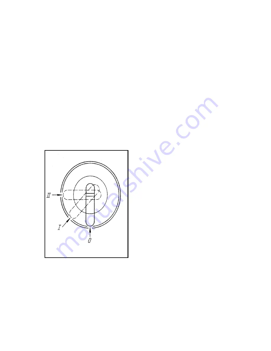
The
ignition lock (19)
has three fixed positions
of the key. The position and switching diagram
of the ignition lock are given in Fig. 2.2-2.
Running position (I)
Voltage is supplied to the
ignition (via the Cutoff Switch), horn, stop
signal switches, neutral pilot lamp, turn
indicator interrupter, and head and tail lamps.
NOTE: (II position is not to be used for US
import models due to DOT regulations but
the switch should not be left in the II
position, which could discharge the battery.
Always turn the key to the O position to
remove the key).
Figure 2
Not used
Position 1
Off position
Summary of Contents for 2000 -10 series
Page 1: ...Year 2000 Repair Manual ...
Page 14: ...Table 1 2 1 cont d Lubrication diagram ...
Page 177: ......
Page 178: ......
Page 179: ......
Page 180: ......
Page 181: ......
Page 182: ......
Page 183: ......
Page 184: ......