


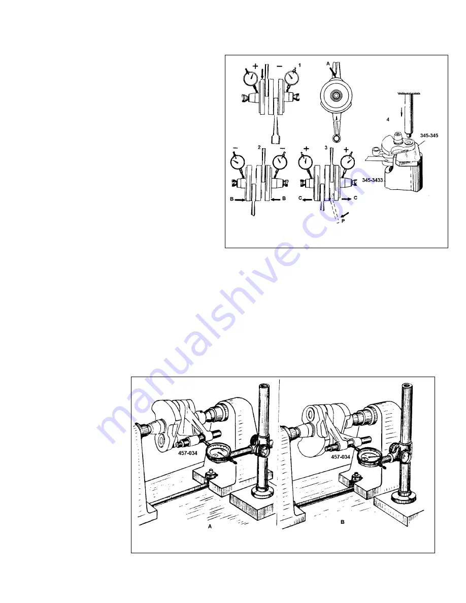
The pointers of both indicators should
deviate in the same sense, i. e. positive or
negative (Fig. 4.8-5, 2
and 3). If the
indicator pointers read different values
(Fig. 4.8-5, 1
),
then determine the peak
point on the crankshaft main journal (1 -
left-hand journal), and, by clamping the
crankshaft cheek in the vice, knock slightly
against the left-hand journal (arrow A,1
).
If the pointers of indicators read the same
negative deviation which exceeds the
tolerated value, then knock inwards as
indicated by arrow (B-2). When the
deviation is positive, spread out the
journals (arrow C
,
3) making use of lever
(P, 3) for the purpose, or press 4.
Measure the turning of the crankpin in the centers using the indicator. Insert mandrel
457-034 into the connecting rod small ends; choose the mandrel color to match that of
the small end holes. Measurements should be taken in two positions of the crankshaft
(Fig. 4.8-6, a and b
).
The difference in measurements should not exceed 0.5 mm / 0.2
in. If otherwise, straighten out the crankshaft by carefully knocking with a copper
hammer against the respective sides of the journals. Thereupon, check the runout of the
main journals.
Check the connecting rod small ends for proper alignment with the crankshaft axis by
sliding the mandrel through both rod ends. If the mandrel will not slide through both
holes, that indicates a bent rod.
If, on disassembly,
the crankshaft is
beyond the service
wear limits, it must be
replaced (see Table
4.8-1).
CAUTION: Do not
attempt to
straighten a
connecting rod,
once the crankshaft
is assembled.
Fig. 4.8-5. Measuring the Runout of
Crankshaft
Fig. 4.8-6. Measuring the Turning of Crankshaft
Summary of Contents for 2000 -10 series
Page 1: ...Year 2000 Repair Manual ...
Page 14: ...Table 1 2 1 cont d Lubrication diagram ...
Page 177: ......
Page 178: ......
Page 179: ......
Page 180: ......
Page 181: ......
Page 182: ......
Page 183: ......
Page 184: ......