background image

w w w . u q d e v i c e s . c o m  


L o g i c 1 6   U s e r   M a n u a l

 | 12 


Continuous    

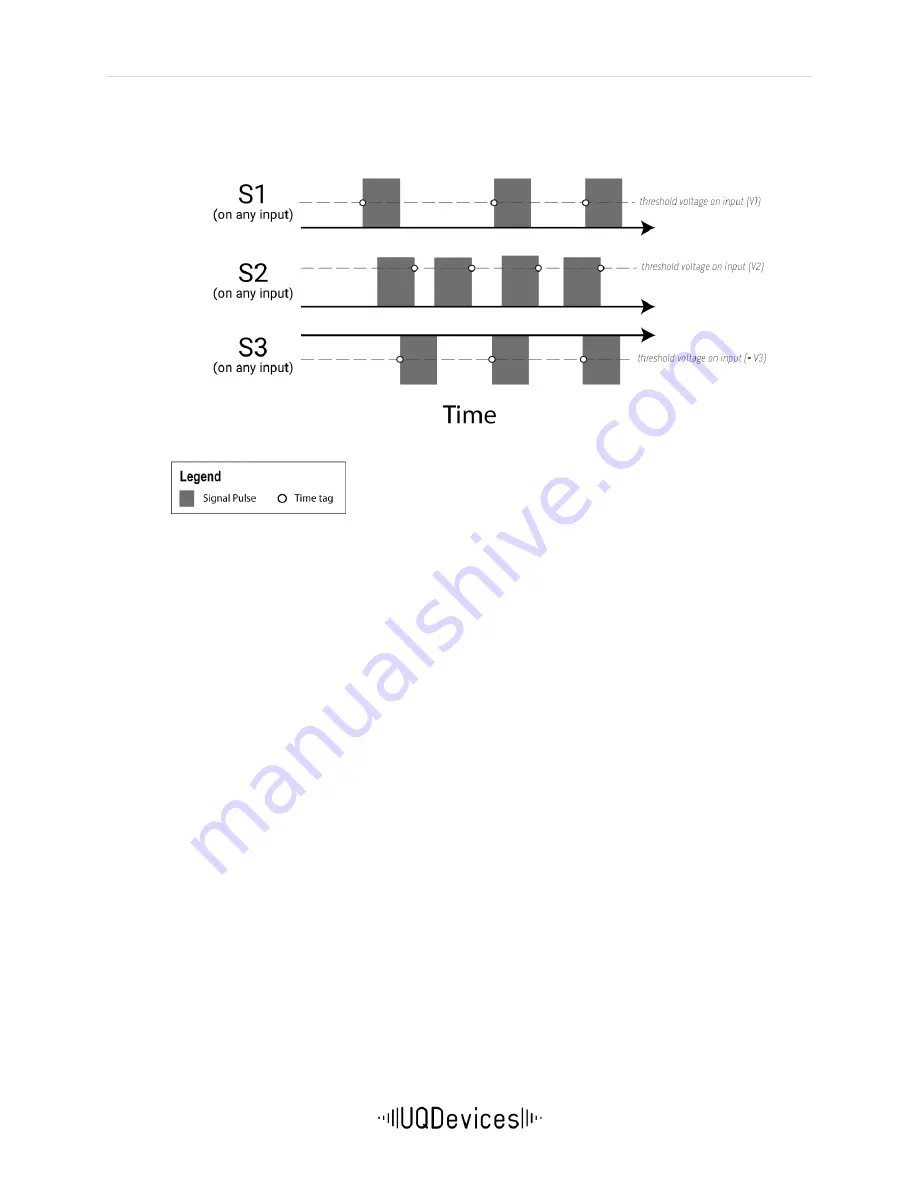
Logic16 streams absolute time tags from ALL detected signals directly to the host PC without any 
filtering or gating.  


Figure 3-I 

Continuous time tagging

: Three  different signals, S1 (rising edge; 

V1),  S2  (falling  edge;  V2)  and  S3  (falling  edge;  -  V3)  are  time  tagged 
concurrently. All pulses are being tagged.   


Time Tag Filter 

The Time Tag Filter can be used to effectively reduce the bandwidth required to perform certain 
measurements. For example, it can enable time of flight (TOF) measurements with respect to fast 
trigger signals (up to 190 MHz), which is too high rate to be recorded in continuous time tag mode. 
This is possible so long as the photon detections of interest do not exceed the data transfer rate 
(11 MHz). The Time Tag Filter can also be used to reduce data file size when recording photon 
events  for  long  periods  of  time  (e.g.,  days),  in  cases  where  only  multi-photon  events  are  of 
interest.  

The filter transmits tags only when signals appear in groups. The user must define the minimum 
number of tags required within a group and the maximum time that can separate adjacent time 
tags.  A group may contain an arbitrary number of tags  greater than or equal to the minimum 
number, as long as the time gap between any two tags is less than the defined maximum time. It 
is therefore important to be mindful that the maximum time must be less than the period of any 
periodic signal input. If the maximum time exceeds the period of a signal, all events will be tagged, 
as in continuous time tag mode.  

Inputs can be excluded from the filter using an exception mask. In this case, the time tags on the 
masked channel will always be transmitted, and not included in the filter. With the time tag filter 
in use, Logic16 can time tag events at 190 MHz, distributed across all channels. Data transfer will 
still occur at up to 11 MHz. 

Caution: Using filter exceptions can cause time tags not to be transmitted in correct order. (e.g. 
Time differences can be negative)  
 

Summary of Contents for Logic16

Page 1: ...Logic16 Time Tag Unit User Manual Version 3 0 ...

Page 2: ...g Unit User Manual Version 3 0 Universal Quantum Devices 295 Hagey Boulevard 1st Floor West Entrance Waterloo ON Canada N2L 6R5 Phone 1 519 778 9146 Email info uqdevices com Web www uqdevices com In collaboration with ...

Page 3: ...GER MODE 11 3 3 3 LOGIC MODE 15 3 3 4 DELAY 17 3 3 5 FUNCTION GENERATOR 17 3 3 6 EXTERNAL CLOCK INPUT 17 3 4 FIRMWARE UPDATE CHANGE 18 SECTION 4 SOFTWARE INTERFACE 20 4 1 DRIVERS INSTALLATION 20 4 1 1 WINDOWS 8 OR HIGHER 20 4 1 2 PRE WINDOWS 8 20 4 1 3 LINUX 20 4 2 GRAPHICAL USER INTERFACE 21 4 2 1 TIMETAG EXPLORER 21 4 2 2 UQD LOGIC16 CORRELATION VIEWER 31 4 3 APPLICATION PROGRAMMING INTERFACE AP...

Page 4: ...gered outputs Since all time correlation processing is performed internally it can be used even with small low power computers Time Tagger Mode time tags photon events in other words it records the input channel and event time when signals are detected In Time Tagger Mode it is possible to perform continuous time tagging time tag each event detected gated time tagging condition time tagging to occ...

Page 5: ...gurations Configuration A has 16 input channels with a resolution of 156 25 ps time bin width while Configuration B has 8 operational input channels with a resolution of 78 125 ps time bin width Unless requested Configuration A is shipped as a default It is easy to switch between the two configurations using a user supplied JTAG cable See Section 3 3 for details ...

Page 6: ...on Programming examples are included on the Logic16 CD which is available at www uqdevices com On the website you will also find video tutorials The success of UQD and DotFAST consulting is based on tight interaction with our customers In the case you experience any problems need clarifications or simply have an idea for improvement contact us by phone 1 519 778 9146 or email info uqdevices com Di...

Page 7: ...lue This quick start guide references the use of Time Tag Explorer See section 4 to learn about Logic16 Correlation Viewer or custom programming iv Connect to a signal Connect one of the input channels to a photon detector using an SMA Cable Alternatively simulate your signal using output 4 a basic function generator6 v Read tags or count patterns Check the Read Tags box on the Time Tag Explorer T...

Page 8: ... Blue when unit has established a successful connection to host PC Error LED Red when an error occurs during operation of the device Note All three LEDs light up briefly upon connection to the power supply This indicates that the power is on and the unit is booting USB port Connection for USB 2 0 cable provided Note We recommend that you do not use a USB Hub in order to connect multiple units to y...

Page 9: ...peration within a NIM crate that is powered with a properly rated and installed power supply In particular in order to ensure safe operation of the logic module and any connected instruments or computers it is critical that the NIM crate and its power supply are connected to electric ground through the power connector as required by the local safety standards DC power supply Only use DC regulated ...

Page 10: ...mber of inputs 16 8 Input definition SMA 50Ω termination DC coupled I P discriminator Threshold range 2 V to 2 V steps of 15 mV Min pulse amplitude 50 mV typical Edge Detection Rising or Falling Min pulse duration above threshold 300 ps Max I P level 2 5 V to 5 0V Counters 32 bit GENERAL Power NIM standard from crate 12V 1 0 A 12V 0 5 A OR DC power supply 12V 1 5A Interface USB 2 0 OTHER I O Exter...

Page 11: ...iples of its internal timing resolution 156 25 ps or 78 125 ps for Configuration A or B respectively Note that in Logic16 there is no designated start channel the reference time is that of the first tag regardless of which input it was detected on In other words the first signal detected will be recorded as occurring at time 0 In Time Tagger Mode Logic16 offers modifiable filtering and gating Empl...

Page 12: ...ys in cases where only multi photon events are of interest The filter transmits tags only when signals appear in groups The user must define the minimum number of tags required within a group and the maximum time that can separate adjacent time tags A group may contain an arbitrary number of tags greater than or equal to the minimum number as long as the time gap between any two tags is less than ...

Page 13: ...input 8 This gate opens for a user specified time after there is an active edge on input 8 The gate width should be less than the period of the trigger signal or the results will be unreliable The position of the gate can be adjusted to compensate for cable delays and similar effects This can be a negative and positive time interval 7 7 In configuration B Logic16 input 8 does not time tag when usi...

Page 14: ... threshold voltage tags are processed normally When it is lower the input signals are ignored Please note that the level gate signal has in internal jitter of 5 ns Disclaimer Level gate starts 25ns before the trigger signal Figure 3 IV Level Gating When Signal S1 on input 9 is higher than the threshold voltage it triggers the level gate open Gate width is the same as the high time of S1 Only pulse...

Page 15: ...ted concurrently on board the unit The coincidence window is the maximum time from the first detection to the last8 in the pattern detection event When all logically selected conditions Ø are met within that time window the event is counted Otherwise the event is not counted The user can modify the coincidence window see specifications Ideally there will not be more than one on a single input with...

Page 16: ... defined in the Logic Pattern section however instead of counting these patterns when they occur registration of an event will trigger the output of a TTL pulse Each output can be set to its own distinct pattern trigger Note that these patterns are also set independent from coincidence counting patterns In other words the user can set any pattern to be counted and any other pattern to trigger an o...

Page 17: ...e change for even larger multi photon experiments as well as long distance synchronization e g in quantum communication including Quantum cryptography and quantum key distribution The 10 MHz input is located on the rear side of the device It can be used to increase the stability of long term measurements by connecting a stable clock source The input is AC coupled For this reason it can be driven b...

Page 18: ...n Tools available for your PC under Vivado HW Developer in ISE Archive o Follow setup instructions given by Xilinx and ensure Xilinx iMPACT is accessible Firmware PROM files provided by UQD found in the CD drive provided Time Tag Explorer optional Perform the following procedures to update change the Firmware i Connect Logic16 to PC with a JTAG Cable Modules manufactured after January 2015 connect...

Page 19: ...t will have its firmware updated Right click on the first device xcf08p and choose Assign new configuration file Choose the desired file mcs file under Firmware from the CD drive provided with the device i e Timetag_230_06_highres mcs Once selected right click again on this device and choose Program The device programming properties will open Select the checkmark beside Verify and click OK Once do...

Page 20: ...evice again 4 1 2 Pre Windows 8 i Extract the Zip file with the USB driver ii Plug the unit into the NIM crate or DC power supply iii Connect the unit to the computer using a USB cable iv Power on the NIM crate v When prompted choose manual driver selection vi Navigate to the folder with the extracted files and open the sub folder USB Driver vii The driver is installed and the device is ready for ...

Page 21: ...ts are installed on your computer Microsoft NET Framework 4 0 The Client Profile version will do It can be downloaded here www microsoft com en US download details aspx id 17718 Microsoft Visual C 2010 Redistributable Package It can be downloaded here www microsoft com en US download details aspx id 5555 NOTE The links in the start menu are renamed each installation You can have several versions o...

Page 22: ...alibration procedure is performed DC Calibrate DC calibration is a useful feature when triggering very small signals near zero DC Calibration only has to be done only once for each unit Before starting DC calibration please make sure that all inputs have zero voltage This is done best by disconnecting all SMA connectors Then press the button DC Cal The following dialog appears Press Ok After a few...

Page 23: ...um number of tags required in one group When the value is 1 all tags are transmitted FilterMaxTime Enter the maximum time interval ns between any two tags within a group Ensure the value is less than period of any of the input signals or else all tags will be transmitted Note A group be of arbitrary length as long as there is no time gap greater than the specified maximum time FilterExceptions Cli...

Page 24: ...s converted to a text file By choosing IncrementName the temporary filename is automatically changed each time Stop is pressed This features is particularly useful in conjunction with the ConvertList feature The Convert List feature automatically converts all temporary files in a certain folder The folder and the file extension are taken from the Temp File text box The text box just has to link to...

Page 25: ... choose to process the raw file format without converting it Note this format could change in future versions The raw file format is a series of 32 bit integers Each integer is divided in two fields Channel The cannel is encoded in the bits 31 26 It is in the range of 0 15 Values higher than 15 have a special meaning see below Special channel numbers 0x1f Dummy Please ignore 0x1e High bit Bits 51 ...

Page 26: ...ting delays between channels The output on the right side gives the single count rates per cycle time and in thousands per second kHz for each Input channel and below the count rates for the arbitrary coincidence patterns Use Logic Check off to start using logic mode Store MinMax Check off to show maximum minimum kHz Approx Cycle time The software tries to read the data with this measurement time ...

Page 27: ...th ns Enter the value of desired pulse high time in ns Output Event Count Enter the number of events you expect to occur in one 5 ns time slice under worst case conditions Increasing the value by one will increase the delay of the outputs by 10 ns Output Coincidence Pattern Set coincidence pattern by clicking on the button to change the state of the corresponding input The input must have an activ...

Page 28: ...UseLevelGate Check off to start level gating The checkbox LevelGateActive is automatically checked when the gate signal is high UseEdgeGate Check off to start edge gating Specify the preferred length of in GateWidth ns The position of the gate can be adjusted to compensate cable delays and similar effects Note that the gate position can be a negative and positive time interval Figure 4 V Gate Tab ...

Page 29: ...function generator located on Output 4 The cycle time and high time can be adjusted in 5 ns increments The actual frequency and duty cycle is calculated and output below the text boxes The values can be adjusted from 10 ns to 1 3 sec Period Enter period of pulses in 5 ns increments High time Enter pulse width required in 5 ns increments Pulse count Enter the number of pulses required 0 generates i...

Page 30: ... Use Histogram Check off to start creating a histogram Accumulate Check off for a cumulative histogram Start Channel Enter the start channel Stop Channel Enter the stop channel Time offset Enter amount of time to offset in resolution time increments Figure 4 VIII Histogram Tab ...

Page 31: ...rrelation_counter exe Using UQD Correlation Viewer Parameters Adjust Input parameters here by changing the following functions Tune channel Enter which channel you would like to adjust You also do this by clicking the channel in the Channel Setting display Threshold V Enter the threshold level in voltage of your input Click All to apply the change to all inputs Delay ns Enter amount of time to del...

Page 32: ...nel To set patterns click the button beside the numbers You have the following options This is the default option This indicates the device will ignore the associated input This indicates the device will count every time there is an active edge on the associated input This indicates the device will count every time there is not an active edge on the associated input You can set up 64 different pat...

Page 33: ...done collecting your data click Saving Click to Stop Correlation Histogram Click Correlation Historgram button to open correlation histogram window Here you can acquire a histogram of time tags of your inputs Histograms settings such as number of bins bin size etc can be adjusted on the right hand side panel The histogram is display on the left hand side The raw data is previewed under CSV Histogr...

Page 34: ...rogramming environments including LabVIEW and C The software interface is contained in the class ttInterface that is present in the file ttInterface dll The dll file can be found in the CD driver provided under the folder named TimeTagExplorer within applications This is only available for Windows LabVIEW Once a new Labview project is opened create a contruct node to access the ttInterface dll You...

Page 35: ... dll through a constructor node Visual Studio C and Visual Basic Once you create a new project access ttInterface dll by adding reference under Project tab Browse to select ttInterface dll from the CD driver Figure 4 XII Visual Studio Add ttInterface dll as a reference in order access all objects and methods ...

Page 36: ...rror conditions an exception of type TimeTag UsbException is thrown Python In Python the NET functions are accessible using the Pythonnet package UQD_Logic_Python_Frequency_Analzyer py is a simple example that shows how to use the UQD logic both in Logic counting mode as well as time tagging mode Note For speed and performance consider using other platforms such as C or VB To access the ttInterfac...

Page 37: ...CTimeTagLibDebug lib Windows 32 bit Win64 CTimeTagLib lib Win64 CTimeTagLibDebug lib Windows 64 bit Linux libtimetag32 so Linux 32 bit Linux libtimetag64 so Linux 64 bit Simple C Program include stdio h include stdlib h include CTimeTag Include CTimeTag h include CTimeTag Include CLogic h using namespace TimeTag CTimeTag timetag timetag Open 1 Open device No 1 timetag Calibrate timetag StartTimeta...

Page 38: ...s open CppDemo sln using Visual Studio 2010 and compile Linux On Linux copy libtimetag32 so or libtimetag64 so to your lib directory If you have not already done so get the g compiler and libusb development version sudo apt get install g 4 6 multilib sudo apt get install libusb 1 0 0 dev Then navigate to the CppDemo folder and type make CppDemo32 or make CppDemo64 To run the program you need admin...

Page 39: ...rface dll NET The constructor takes a ttInterface object which must be already created and creates a Logic object The ttInterface object can already be opened or not Logic Mode Syntax C myLogic new Logic myTagger VB myLogic New Logic myTagger Python myLogic Logic myTagger CTimeTag This class is only for C which must be initialised in order to access all functions required to operate the device Syn...

Page 40: ...cute When the calibration is used it should be the first function to be called after the Open function Note Intrinsic delays of each input may vary after the calibration procedure is performed Syntax C myTagger Calibrate C timetag Calibrate Close This function should be called before the program terminates Syntax C myTagger Close C timetag Close SetLedBrightness int percent The Brightness of the L...

Page 41: ...It should be used to calculate absolute time values The function returns either 78 125E 12 or 156 25E 12 seconds Syntax C myTagger GetResolution C timetag GetResolution GetNoInputs This function returns the number of inputs installed on the device It is used for debugging purposes only Syntax C myTagger GetNoInputs C timetag GetNoInputs ...

Page 42: ... mask C timetag SetInversionMask int mask SetDelay int input int delay All input signals can be delayed internally This is useful to compensate external cable delays Input 1 16 Number of the input to change Delay 18 bit value Delay in internal units See GetResolution Syntax C myTagger SetDelay int input int delay C timetag SetDelay int input int delay SetFG int period int high This function define...

Page 43: ... bool use FreezeSingleCounter This function stores all the single counters synchronously This function also returns the time between the last two calls to FreezeSingleCounter The time is expressed in 5 ns ticks Syntax C myTagger FreezeSingleCounter C timetag FreezeSingleCounter GetSingleCount int input This returns the number of input pulses in between the last two calls of FreezeSingleCounter Thi...

Page 44: ...n internal units 78 125 or 156 25 ps Channel n is the number of the corresponding input The first input is number 1 The array is sorted by time When two tags occur at the same time then the tag with the smaller channel number is transmitted first The arrays can be used until the next call of ReadTags When the data is needed for a longer time it has to be copied to a different array The array is al...

Page 45: ...erMinCount int MinCount C timetag SetFilterMinCount int MinCount SetFilterMaxTime int MaxTime MaxTime defines the maximum time between two pulses in the same group When the time between two pulses is bigger than MaxTime the two pulses are considered to be in different groups MaxTime is given in internal units Example When FilterMinCount is 10 and FilterMaxTime is 1 μs then the maximum possible gro...

Page 46: ...en the gate input is high Syntax C myTagger UseLevelGate bool C timetag UseLevelGate bool LevelGateActive Returns true when the gate input is above the input threshold Syntax C myTagger LevelGateActive C timetag LevelGateActive Edge Gate This gating offers fine grained timing control and very low jitter The width of the gating window can be adjusted in steps of the internal resolution The position...

Page 47: ... to save data to disk The data is saved in a compressed binary format and can be converted to ASCII offline This way the full rate of 11 MHz can be saved to disk on a modern computer It is best explained by an example Saving TTInterface tti new TTInterface tti Open TimeTagReader r tti GetReader r StartSaving rawdatafile tt Wait some time Monitor r SavedTags when you like r StopSaving tti Close Con...

Page 48: ...nversion Mode The generated file can be either text or binary Binary mode is selected by r SetConversionBinary true The default is text mode The interface functions are located in the dll ttInterface dll There is also support for C both for Windows and Linux environments ...

Page 49: ...d data Note The device uses a double buffered memory system The new measurement starts immediately and is running in the background during the call to ReadLogic For this reason not a single pulse is omitted during readout Syntax C myLogic ReadLogic C logic ReadLogic CalcCount int pos int neg This method operates on the data read by the last call to ReadLogic It calculates how often a certain event...

Page 50: ...s called will vary over time because of the limited realtime performance of personal computers The correct count rates can be obtained when the count values from CalcCount are divided by the result from GetTimeCounter Syntax C myLogic GetTimeCounter C logic GetTimeCounter Outputs SetOutputEventCount int events This function is an advanced feature that can be used to fine tune the delay of the outp...

Page 51: ...vent of the inputs that must be present with range 0 65535 as for CalcCount The parameter neg is the bit coded value of the Coincidence Event of the inputs that must not be present with range 0 65535 Method Call Result SetOutputPattern 1 1 0 Output 1 fires when input 1 is present SetOutputPattern 2 6 0 Output 2 fires when inputs 2 and 3 are present within the coincidence window SetOutputPattern 3 ...

Page 52: ...rnal reason should never occur 3 8 DoubleError One input had two pulses within the coincidence window 4 16 InputFifoOverflow More than 1024 successive tags were detected with a rate greater 100 MHz 5 32 10MHzHardError The 10 MHz input is not connected or connected to a wrong type of signal 6 64 10MHzSoftError The 10 MHz input is connected but the frequency is not 10 MHz 7 128 OutFifoOverflow Inter...

Page 53: ...1_Load sender As Object e As EventArgs Handles MyBase Load Dim Singles1 Singles2 Coincidences As Integer Dim FPGA_v TimerCounter As Double open connection to device myTagger New TTInterface myTagger Open get some basic info and display Resolution myTagger GetResolution FPGA_v myTagger GetFpgaVersion MsgBox FPGA Version FPGA_v ToString vbCrLf _ Timing Resolution Resolution ToString s vbCrLf vbCrLf ...

Page 54: ...er 0 000000005 retrive observed counts for singles 1 2 and coincidences 12 singles1 mylogic CalcCountPos 1 singles2 mylogic CalcCountPos 2 coincidences mylogic CalcCountPos 3 show data MsgBox Measurment Time vbTab vbTab TimerCounter ToString F4 s vbCrLf _ Singles Channel 1 vbTab vbTab Singles1 ToString vbCrLf _ Singles Channel 2 vbTab vbTab Singles2 ToString vbCrLf _ Coincidences Chs 1 2 vbTab Coi...

Page 55: ...w w w u q d e v i c e s c o m L o g i c 1 6 U s e r M a n u a l 55 LabVIEW Sample Program ...

Page 56: ...nit s resolution Counts Counts displays the number of events in the last Measurement Time corresponding to a given logic pattern Logic Pattern Logic Pattern is the pattern of coincidences to report in counts Channel 1 is the leftmost button and channel 6 is the rightmost expand the control to see more channels Green means an event on the channel must be present red means an event on the channel mu...

Page 57: ...c Unit in nanoseconds Coinc Window controls the time window in nanoseconds within which counts on different channels are counted as coincident Actual Coinc Window reports the coincidence window actually used in nanoseconds which must be a multiple of the Coincidence Logic Unit s resolution Measurement Time chooses the time in seconds between reading the Coincidence Logic Unit s buffer meaning Coun...

Page 58: ...der using the integrated pulse generator and coincidence triggered outputs to control gating How can I switch between the Logic16 Configuration A 156 ps 16 channel and B 78 ps 8 channel Switching configurations requires updating the firmware of the FPGA that is housed within the Logic16 unit This can be done by the user in lab but not during a measurement How can I record time tags over many hours...

Page 59: ...ed for initial set up trouble shooting but does not provide data acquisition saving capability UQD Logic Counter basic coincidence counting and data recording Customization UQDevices suggests that experimentalists develop a customized data acquisition software in their preferred DAQ environment LabView C Matlab etc If you have questions requests or feedback regarding available software please cont...

Page 60: ...g i c 1 6 U s e r M a n u a l 60 Section 6 Revision History Date Document Version FPGA Version Dll Version Remark 2019 12 20 3 0 2 30 2 30 User Manual Version 3 0 is a combination of Time Tag User Manual 2_3 and Logic User Manual 1_5_2 ...

Reviews: